Pedestal Design per Eurocode 2 for Isolated Footings
For isolated footings, design of the pedestal is performed per the Eurocode 2 code, BS EN-1992-1-1: 2004, with the British Annex.
Design as a Column
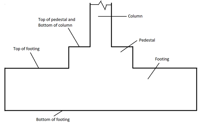
For each strength load case contained in the job for that footing, the pedestal is designed at 2 locations - top and bottom.
Top is defined as the point where the column ends and the pedestal begins.
Bottom is defined as the bottom of the footing.
Thus, the pedestal is treated as a column whose height is equal to the distance from the bottom of the column to the bottom of the footing.
At the top of the pedestal, the forces and moments used in the design are the column reactions which can be viewed in the Loads & Factors table
The forces and moments acting at the bottom of the pedestal are derived from those at the top by (a) adding the selfweight of the pedestal to the FY force at the top (b) adding the moments due to the lateral forces FX and FZ acting at the top of the pedestal. To these moments, additional moments as described next, if applicable, are added.
So, for each strength load case, the aggregate moments along with the axial force for that load case are used to check the suitability of the cross section at both ends (top and bottom) using the interaction method, and, the appropriate amount of reinforcement required for that load case is determined. The highest area of steel from all the strength load cases is deemed the steel required for the pedestal, and the corresponding load case is identified as the critical load case.
Design for Shear
The shear force carrying capacity of the section without shear reinforcement is determined for both directions from Clause 6.2.2 of EC2. If the applied shear force exceeds the capacity, the stirrup requirement is computed.
A design summary that is presented in the calculation sheet is shown below.

The following are some of the terms that appear in the output and their meaning:
For capacity ratios:
- Flexural capacity ratio
- = Mres / Mcap
where
- Mres
= - resultant moment = √(Ma2 + Mb2) calculated from final moments Ma and Mb about the two principal axes (including slenderness and other criteria)
- Mcap
= - Moment capacity of the section from the P-M curve
- Axial capacity ratio
- = Pmax / Pu
where
- Pmax
= - maximum axial force on the column from all load combination
- Pu
= - Axial capacity of the column calculated using below formula
= [(0.4 × fck × Ac) + (0.8 × Fy - 0.4 × fck) * Ast]
- fck
= - concrete grade
- fy
= - steel grade
- Ac
= - area of concrete
- Ast
= - area of steel
For shear design:
- VRD,c
- Design value of shear resistance as per Clause 6.2.2 of EC2
- As Tension
- the term, Asl, described in Clause 6.2.2, BS EN 1992-1-1:2004
- CRdc
- Intermediate parameter for shear calculation, (See Note at the bottom of Cl. 6.2.2, BS EN 1992-1-1:2004)
- deff
- effective depth (distance from cg of tensile reinforcement to extreme compression fiber
- k
- = Min(1+√(200/deff), 2) as per Clause 6.2.2 of EC2
- ρ1
- = As Tension /(b × deff)
- k1
- See Note at the bottom of Cl. 6.2.2, BS EN 1992-1-1:2004
- σcp
- Ned/(B×D)
where
- Ned
= - Axial force in the section
- B and D
= - the smaller and larger dimensions of the cross section respectively
Axial Load and Biaxial Bending Design
- λD
- slenderness ratio about the side D which is the side whose length is the longer dimension of the cross section
- λB
- slenderness ratio about the side B which is the side whose length is the shorter dimension of the cross section
- eD(top)
- eccentricity at top of pedestal along the direction parallel to the "D" side
- eD(bottom)
- eccentricity at bottom of pedestal along the direction parallel to the "D" side
- eB(top)
- eccentricity at top of pedestal along the direction parallel to the "B" side
- eB(bottom)
- eccentricity at bottom of pedestal along the direction parallel to the "B" side
- Biaxial bending ratio
- = (MD/McapD) + (MB /McapB)
where
- MD
= - moment about the axis parallel to the longer side
- McapD
= - moment capacity about the axis parallel to the longer side
- MB
= - moment about the axis parallel to the shorter side
- McapB
= - moment capacity about the axis parallel to the shorter side