Calculating the Factors of Safety for Mat Foundations
The topic details the procedure used by the program to calculate the factor of safety in sliding and overturning for mat foundations (also referred to as stability checks).
Check for Sliding
The procedure used in the sliding check is as follows. In this description, the global X direction is used to illustrate the method. A similar procedure is used for global Z.
- Calculation of disturbing force
Find the total of the horizontal forces FX that is acting on the foundation from all the columns located on the mat. Let us call this Total_FX_applied.
- Calculation of resisting force
Find the total of the vertical forces FY that is acting on the foundation from all the columns located on the mat. Let us call this Total_FY_applied.
Total vertical load = selfweight of mat + weight of soil on top of mat + weight of pedestals + Total_FY
Total horizontal resistance in X direction = Coefficient of friction × Total vertical load
The coefficient of friction is specified through the Default properties tab under the mat foundation job as shown in the next figure.
- Calculation of factor of safety
Factor of safety in sliding along X = (Total horizontal resistance in X direction) / Total_FX_applied
Check for Overturning
The procedure used in the overturning check is as follows. In this description, the global X direction is used to illustrate the method. A similar procedure is used for global Z.
- Calculation of Overturning moment
whereOverturning moment = Moment_Part_A = M1 + M2 - M1
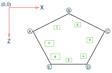
= - summation of all the MX moments acting at the base of the columns. In the attached figure, it will be equal to
MX_column 1 + MX_column 2 + MX_column 3 + MX_column 4 + MX_column 5 + MX_column 6 + MX_column 7
- Term_C
= - shear force FZ at the base of the column multiplied by (height of pedestal + thickness of mat slab)
- M2
= - summation over all the columns of this Term_C
If Moment_Part_A is positive, calculate FOS about the point on the slab that is farthest along the Z direction from the origin (Corners D or E in the attached figure)
If Moment_Part_A is negative, calculate FOS about the point on the slab that is nearest along the Z direction from the origin (Corner B in the attached figure)
The corner that is decided upon from the above step is called the critical corner.
- Calculation of
Restoring moment
whereRetoring moment = Moment_Part_B = M3 + M4 + M5 - M6 + M7 - M3
= - moment due to weight of the slab + the soil on top of the slab
Assuming that the finite element mesh of the slab is known, for each element, find the product of its area and density of concrete.
The weight of soil on each element is equal to
the area of the element × the unit weight of soil × the height of soil above the slab
The sum of the above weights is to be multiplied by the distance along the Z axis of the element's CG from the critical corner.
The summation of this moment across all the elements is called M3.
- M4
= - moment due to the axial load FY coming through the columns from the superstructure
For each column, find the distance along the Z axis of the Z coordinate of its base from the critical corner. If the axial load is acting downwards, it will produce a moment that has the same sign as M3. If the load acts upwards, it will have a sign opposite to that of M3.
- M5
= - moment due to weight of the pedestals. Calculate the weight of each pedestal. Lever arm is the same as that calculated for the quantity M4. Summation over all the columns of the weight of the pedestal × Lever arm will give M5.
- M6
= - moment due to weight of soil displaced by the pedestal = Cross section Area of pedestal × height of soil above slab × lever arm. Lever arm for the individual pedestals is the same as that calculated for M4 or M5. Summation of this moment across all the columns give M6.
- M7
= - Moment due to pressure loads and point loads applied directly on the mat. Loads acting downward will add to the restoring moment, while loads acting upward will reduce the overall moment.
- Factor of safety
Factor of safety = Moment_Part_B divided by Moment_Part_A
Output
In the calculation, the output along the lines shown in the next figure is presented for each service load case. If the model does not contain any service load cases, the above checks are not performed, and the calculation sheet will not contain this output.
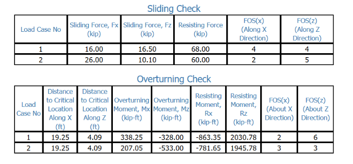
In this output, the terms "Distance to critical location along X" and "Distance to critical location along Z" are the distances from the origin (X=0, Z=0) to the point about which the overturning check is performed. Resisting Moment stands for the restoring moment. FOS stands for factor of safety.
Notes
- Stability checks are performed only for mats for which soil is the only support (also known as raft foundations). If pile springs are included in the model, due to which the model becomes a mat on piles or a raft on piles, the stability checks are not performed.
- The following
is a summary of the manner in which the various forces that act on the mat
foundation from a column/pedestal are used in the stability checks.
- FX and FZ are treated as contributing to the "Sliding force" for the Sliding Check, and to the "Overturning Moment" for the overturning check.
- MX and MZ are treated as contributing to the "Overturning Moment" for the overturning check.
- FY is treated as contributing to the "Resisting Force" for the Sliding Check, and to the "Resisting Moment" for the overturning check.
For all of the above column forces/moments, depending on their sign (positive or negative), their contribution may be additive or subtractive to the result term they are considered for, depending on the location of the edge where the check is performed.
- Starting from version 09.xx.xx.xx of the program, the selfweight of the mat, and the weight of soil on top of the mat are considered as contributing to the "Resisting Force" for the Sliding Check, and to the "Resisting Moment" for the overturning check, only if, the Dead Weight factor is set to non-zero in the Apply Self weight and Dead Weight factor table for the associated service load case. Those weights are factored by the value specified for Dead weight factor.