Concentrated Loads
Concentrated loads are forces and moments acting either on structural nodes, or on structural elements at the position defined by the length ratio x/l. In case of element loads, the loading direction may be defined in terms of the global or of the local coordinate system.
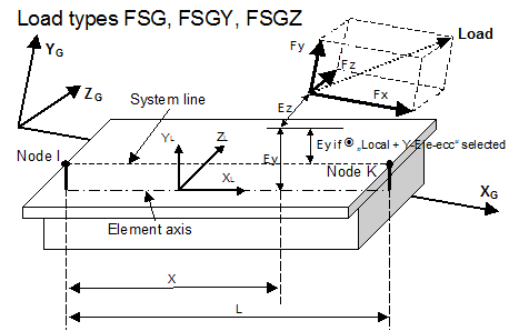
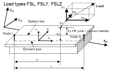
Single element load with force – load types FSG, FSGY, FSGZ, FSL, FSLY, FSLZ
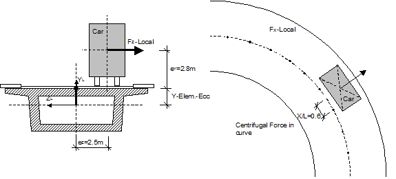
These load types define concentrated forces acting at the position x/l relative to the start point of an element. The loading is specified by defining the 3 force components in the local (L) or global (G) coordinate directions (Fx, Fy, Fz), the location in the element (x/l), and any eccentricity of the application point in the local y or z direction (Ey, Ez).
Application example 2: Braking force in accordance with AUSTRIAN Standard
25 t Truck ≥ braking force: 0.3×250 = 75 kN
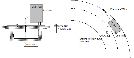
Example braking force on a curved bridge
FX-LOCAL=75 [kN], eccentricity = Y-ELem.ecc.+ey (=+0.15m), ez=-2.5mApplication example: This load type will be typically and advantageously used in the case, where horizontal structural eccentricities exist, and the given horizontal load eccentricity is related to the connection line of start and end nodes rather, than to the centroid line.
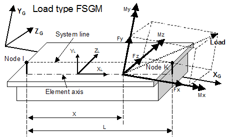
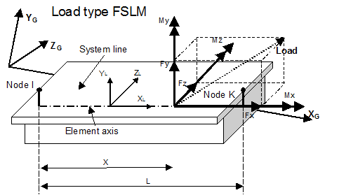
Single element loads (Forces+Moment) – load types FSGM, FSLM
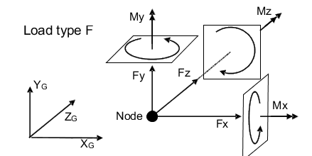
These two load types specify the full force vector consisting of 3 force components (Fx, Fy, Fz) and 3 moments (Mx, My, Mz). The terms may be specified either in global directions (load type FSGM), or in local element coordinate directions (load type FSLM). The position in the element is defined by specifying the relative distance x/l to the element begin.
Single element load as nodal load – load type FSY
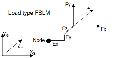
This load type has been provided with in-situ segmental cantilever construction in mind. Defining the specific weight of the material (Gam) for a series of new inactive elements (e.g. for simulating the ‘wet concrete’ weight) allows for applying the total weight of this element series on a particular node (Nod), if necessary with taking into account an eccentric application point (Ex, Ey, Ez). The eccentricity is specified in terms of components in global coordinate directions (from the node to the center of gravity of the load).
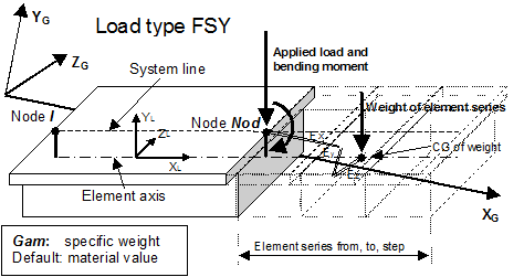
Note that a positive value of Gam will yield a force in the negative global Y-direction. The definition of the eccentricity ECC2 is currently obsolete, i.e. the moment due to the eccentric loading will be applied as nodal moment at the specified node Nod. In order to allow for applying the wet concrete load as a pair of vertical loads acting at the anchor points of the traveller carrying the falsework, the below described load types FSEGB and FSEGE have been provided.
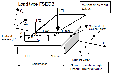
Single element load as nodal load at end of segment – load type FSEGE
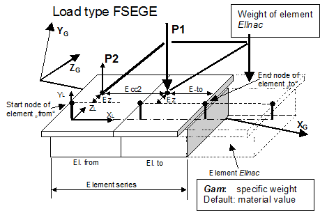
The load types FSEGB and FSEGE have been provided to improve the original wet concrete load definition facility FSY. FSEGB and FSEGE allow for applying the wet concrete load of new elements as a pair of vertical loads acting at the anchorage points of the traveller rather than as load plus moment acting at an appropriate structural node.
The input values From, To, Step specify the range of elements, where the load application points can be located. Using the input values E-from (or E-to respectively) and Ecc2 as shown in Figure 1-10 and Figure 1-11, the program searches in this range the element where the self-weight of the new element (ElInac) is applied. An eccentric location of the load application points can be considered by specifying the appropriate eccentricity value Ez in local z direction. The eccentricities of the two load application points must essentially be the same.
The element range definition From, To, Step must be given in positive local x-direction. The load type FSEGB must be used, when the new element is connected to the start node of the From element, and FSEGE must be used, when the new element is connected to the end node of the To element. Therefore, the From (in FSEGB) or To element (in FSEGE) must essentially be the elements, where the new element is connected, even if the distance of the 1st load application point is greater than the element length.
The weight of this element is calculated with using the specified specific weight value (Gam) and the geometric parameters stored in the database. The value Gamma of the material table is used, if Gam is not specified.
The location of the center of gravity of the new element is calculated automatically, i.e. the program is able to calculate the appropriate traveller anchorage forces and to apply them at the specified load application points as concentrated load in element.
Note that a positive value of Gam will yield a total force in negative global Y-direction, resulting in a downward load at the 1st and an upward load at the 2nd load application point.