Design Wind Load Cases (Section 27.3.5)
Load cases for buildings with any heights are created according to design wind load cases given in Figure 27.3-8. The figure contains four cases but they are expanded to 12 cases when both X-axis and Y-axis are selected. If only X-axis or only Y-axis is selected, only the corresponding directions of Case 1 and Case 2 are created.
If the option Exempted from Torsional Cases 2 and 4 per Appendix D is selected, those laod cases will not be generated. This option should only be selected if it has been determined that the requirements of Appendix D have been satisfied.
It should be noted that eccentricities for X and Y directions are defined respectively with ±0.15 Bx and ±0.15 By for rigid buildings, where B is the building dimension perpendicular to the wind direction. If the building is flexible in that direction, eccentricities are calculated with respect to the following equation:
| (27.3-4) |
| = |
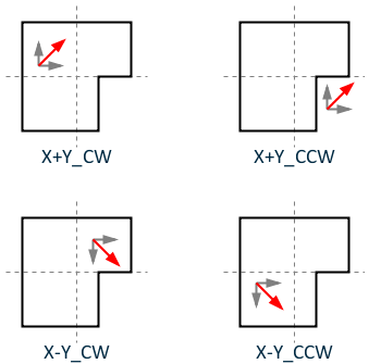
The program automatically creates a load case for calculation of center of rigidity if it is a flexible building. The eccentrically applied loads in both directions are shown below. These load cases correspond to Case 4 in Figure 27.3-8.