Loads on Diaphragms (Physical and Mass Loads)
Once a diaphragm is meshed and represented with a collection of shells, all loads on the diaphragm are converted to point loads which are directly applied to the shells. The loads on diaphragms are simply surface, line or point loads as defined in the Modeler. Any overlapped surface loads are automatically resolved. Both mass loads and physical loads are processed the same way. The program can also include self weights and mass from elements including decks.
In the following figures, mass loads are shown but physical loads are also processed the same way.
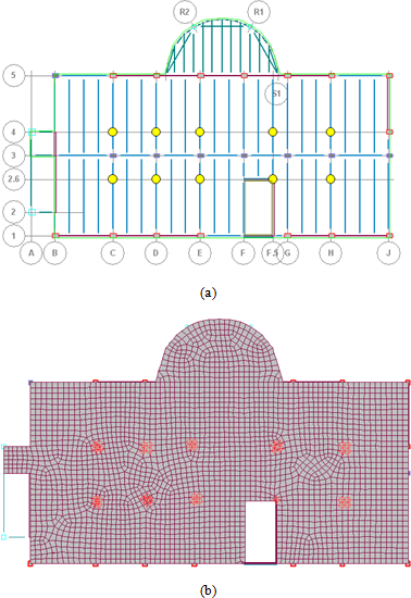
- Line Loads: they are directly applied to the meshed surface. The program converts line loads into equivalent point loads which are applied to shells' nodes (note that if a line load is crossing any shell element, then the portion of the line load located inside the shell is extrapolated to the shell's nodes as equivalent nodal loads). An example is given in Figure 6‑48.
- Point Loads: They are directly applied to the meshed surface. If point load is located directly on a shell node, it is applied to the node directly. If the point load is located inside a shell element, it is extrapolated to the shell's nodes as equivalent nodal loads. An example is given in Figure 6‑49.
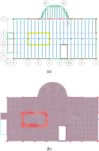
- Surface Loads: They are also applied to mesh nodes. The program first detects overlapping surface load areas (the surface load placed last or at very top is considered as active load). Each surface load on each shell is calculated and then, it is converted to equivalent point loads to be applied at the shell's nodes. An example is given in Figure 6‑50.
- Members' Self weight and Mass: They are directly applied to the members as point loads. This includes all gravity and lateral beams, columns and walls. An example is given in Figure 6‑51.
- Self weight and mass for Decks: Similarly, if deck mass is included in analysis, it is again treated as a surface load and applied to the meshed surface.
Regarding diaphragm masses, two additional options are provided to the user:
- Use Calculated: the program processes all masses related loads according to the procedure explained above. In contrast to rigid diaphragm approach where diaphragm mass is lumped at diaphragm mass center, this procedure considers a spatial mass distribution over semirigid diaphragms.
- Uniformly Distribute Total Mass Over Diaphragm: The total mass calculated for the diaphragm is distributed to shell elements based on each shell’s effective area. This method can be used if a truly uniform mass distribution over the diaphragm exists. Also, it is provided as a alternative method if Use Calculated method fails to resolve mass polygons over the diaphragm due to some numerical difficulties.
Line load example, (a) Applied line loads (indicated with yellow lines), (b) converted to point loads applied to mesh nodes directly