Axial/Flexural Strength
This section discusses the axial-flexural checks that are implemented within the RAM Concrete Wall module and the assumptions made by the program when performing the necessary calculations. Table below provides a summary of the sections of ACI 318-11 covering axial-flexural evaluation that have been implemented within the program.
| Code Section | Limit Check | Referenced Code Sections |
|---|---|---|
| 10.3.1 | Behavioral assumptions | 10.2 |
| 10.3.5 | Minimum steel strain at nominal strength | - |
| 10.3.6 | Maximum design axial strength | - |
| 10.3.7 | Basis of flexural strength | - |
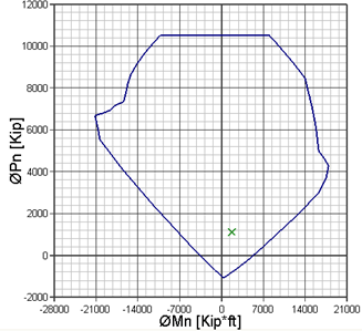
The axial-flexural evaluation of a Section Cut is conducted by generating a three-dimensional interaction capacity surface where axial load is the ordinate and the moments about the Section Cut major and minor axes are the abscissa values. The combined loads acting at each Section Cut are plotted in the P-M-M space to determine if the Section Cut passes the check.
The interaction value for each load combination is calculated as the ratio of the distance in P-M space to the ultimate load data point, LD, to the distance to the intersection of the capacity surface, LC (see Figure below). An interaction value in excess of 1.0 is considered a design failure.

Axial-flexural capacity calculations use net thickness of the section cut, that means that when reveal depths are assigned to a wall panel (See Assign Wall Panel Reveal Depth), the axial-flexural capacity will not consider the concrete section of the reveals.