RAM Steel Column Design
The RAM Steel Column Module is the module where gravity columns and gravity base plates are optimized. Unsized lateral columns are also assigned a preliminary size. All columns in this module are assumed to be simply supported and they are designed for Dead and Live Load applied on one-way decks only. Base plates are optimized for Dead and Live Load only although the columns will be designed for moments induced by the eccentricity of the supported beam connections. This section can only be completed if you have installed the RAM Steel program and have a license available. To invoke the Steel Column module from RAM Manager:
- Select from the Manager. You can also click the third square button on the left side depicting a steel column and Base Plate.
The graphical area will then show a 3D view of the building with the steel columns show in design colors and the other members in grey. You might think of them as status colors. The various colors and the meanings are listed below. (Note that you should only see yellow steel columns upon entering the steel column program with the tutorial model).
A third color option called Interaction Colors is available after the columns have been designed.
Besides altering colors, you may also want to change the information or members displayed in the graphics window. To alter the text or members that are shown:
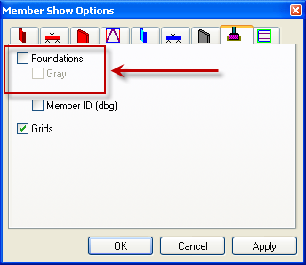
This dialog box is organized by the various types of members. Each can be labeled with a variety of labels or turned off completely.
Sometimes it’s easier to work in Plan or Elevation mode than in 3D. If that’s the case you can select View – Elevation or View – Plan. An additional option in the Steel Column module is to View – Column Plan. This takes you to a compressed aerial view where you can see the entire 3D structure from above with no perspective.
As with the Beam design module, a light in the lower right corner indicates the current status of the file. When the designs are all current the light will be green.