Assign Menu Options
In order for the program to perform a Finite Element Analysis, every lateral member must have an assigned size. For our model, that was initially done in the Modeler, but the assign menu in RAM Frame can also be used to assign sizes to lateral members as we will illustrate below for braces we want to make Buckling Restrained Braces.
Buckling Restrained Braces require you to designate a section that is appropriate for the core (yielding section) of the Buckling Restrained Brace. In this model we will assign a solid rod to the bottom braces of the Frame along Grid F and a flat bar to the braces of the level above. This frame will become our Buckling Restrained Brace Frame.
To Assign a Round Bar to the bottom braces.
- Select View-Elevation and click on any beam in the frame along Grid F (the chevron braced frame).
- Select .
- Select the Material, Shape and Size as illustrated.
- Click Assign [Fence]

The Fence cursor will appear, fence the braces of the lower chevron braces.
Repeat this exercise to assign a flat plate (1/2x6) to the next level of chevron braces to end up with a frame sizes as shown below.

Obviously these braces are small and slender so to appropriately design we designate these as Buckling Restrained Braces.
- If you are not still in elevation mode select View-Elevation and click on any beam in the frame along Grid F (the chevron braced frame).
- Select .
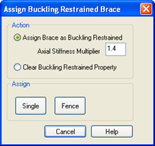
- Select Assign Brace as Buckling Restrained
- Enter 1.4 for Axial Stiffness Multiplier.
- Click Assign [Fence].
- In the graphics mode, Fence all of the lower two chevron braced frame stories.
As the assignments are made, a symbol illustrated above will appear in the middle of the Buckling Restrained Brace with the assigned multiplier value shown.

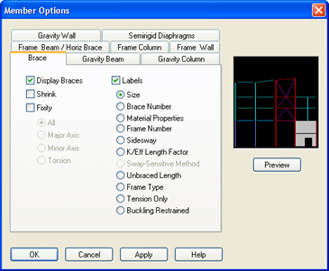
When complete if you want to turn off the labels:
To learn more about buckling restrained braces and their impact on analysis and design refer to the RAM Frame Steel Design Manual.
A variety of information, including the tension-only symbols, the member sizes, end fixity, etc. can all be displayed on screen using the command View – Members  similar to the Steel Column module command of the same name.
The assign menu commands can also use used to assign diaphragm connections, frame numbers, wall group numbers and foundations springs.