Stress and Force Contours
The program stores forces and stresses for walls/diaphragms during analysis if the option to store wall/diaphragm stresses and internal forces is selected before analysis is started (see Criteria – General – Wall/Diaphragm). These results can be displayed on structure by invoking Process - Results - Stress and Internal Force Contours menu command (also it is available in the toolbar).
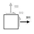
Stresses are normal, shear and out-of-plane (transverse) stresses and they are expressed as force per unit area. They are first calculated at shell integration points and then, they are extrapolated to shell corner nodes. Shell stresses are calculated at both top/positive and bottom/negative faces.
Internal Forces (also known as shell resultants) are forces and moments resulted from integrating stresses over shell thickness. They are expressed as forces and moments per unit of in-plane length.
By default, stress/internal force values are averaged at nodes and contour plots are displayed accordingly. It is possible to show results per each shell element by not selecting Stress Averaging option in the Stress and Internal Force dialog. The option Show Stress contour values can be used to show stress\internal force values on screen (they always represent stresses/internal forces values calculated at shell nodes). In addition, it is possible to display stress/internal force on deformed shape for selected load case/combo (see the option Display on Deformed Shape).
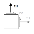
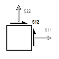
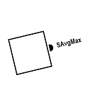
It is important to note that averaged max/min values (such as SMax/SMin or FMax/FMin) are calculated from averaged values of S11, S22 and S12 (or F11, F22 and F12) at nodes.
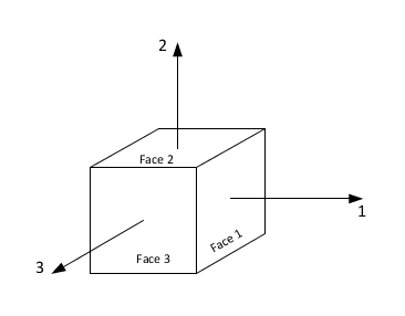
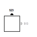
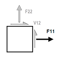
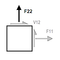
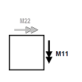
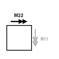
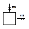
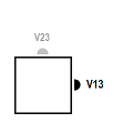
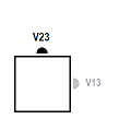
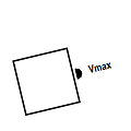
In the following discussions, we refer to the following figure:
Wall and Diaphragm Stresses
Stresses displayed on screen are shown as force per unit area. They are acting on Top/Positive or Bottom/Negative face of shell element.
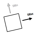


- Principal normal stresses are oriented in such a way that associated shearing stress is zero.
- Maximum principal shear
stress is calculated as follows:
where
- ,
= - principal maximum and minimum normal stresses, respectively
- Von Mises
principal stress is calculated as follows:
where
- ,
= - principal maximum and minimum normal stresses, respectively

Wall and Diaphragm Internal Forces
Internal Forces displayed on screen are shown as force per unit of in-plane length. They are acting at mid-surface of shell element.

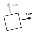

- Principal normal forces are oriented in such a way that associated shearing force is zero.
- Von Mises
principal force is calculated as follows:
where
- ,
= - principal maximum and minimum normal forces, respectively


Stress and Internal Force Contours on Wall and Diaphragm
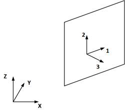
Stresses and internal forces are direction dependent quantities. They are portrayed graphically according to local axes of walls and diaphragms. Local axes of walls and diaphragms are defined as follows (in the following descriptions, right-hand-rule is adapted and, local axes 1, 2 and 3 are perpendicular to each other):
- Wall
-
Local axis 1 and 2 are on plane of wall and local axis 3 is perpendicular to plane of wall. Local axis 2 is always oriented along global axis Z (also note that e2 = e3 x e1). Top (or positive) face of wall is in the direction of positive local axis 3.
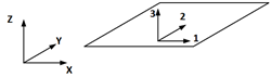
- Diaphragm with Composite Floor Deck/Slab
-
If the option Apply Stiffness Modification Factors is selected (see Deck/Slab Property Information dialog in RAM Manager), local axis 1 is in the direction of deck orientation. Local axis 3 is perpendicular to plane of deck. Local axis 2 is constructed from other axes as follows: e2 = e3 x e1.
If the option is not selected, local axes 1, 2 and 3 are in the direction of global axes X, Y and Z, respectively. Top (or positive) face of diaphragm is in the direction of positive local axis 3.
- Diaphragm with Noncomposite Floor Deck/Slab
-
If the option Apply Stiffness Modification Factors is selected (see Deck/Slab Property Information dialog in RAM Manager), local axis 1 is either in the direction of deck orientation (if deck is one-way) or it is defined at user-defined angle measured from global axis (if deck is two-way). Local axis 3 is always perpendicular to plane of deck. Local axis 2 is constructed from other axes as follows: e2 = e3 x e1. If the option is not selected, local axes 1, 2 and 3 are in the direction of global axes X, Y and Z, respectively. Top (or positive) face of diaphragm is in the direction of positive local axis 3.
- Diaphragm with Concrete Slab
-
If the option Stiffness Modifiers is selected (see Deck/Slab Property Information dialog in RAM Manager), local axis 1 is either in the direction of deck orientation (if deck is one-way) or it is defined at user-defined angle measured from global axis (if deck is two-way). Local axis 3 is always perpendicular to plane of deck. Local axis 2 is constructed from other axes as follows: e2 = e3 x e1.
If the option Crack Factors is selected, local axes 1, 2 and 3 are in the direction of global axes X, Y and Z, respectively. Top (or positive) face of diaphragm is in the direction of positive local axis 3.