Equivalent Static Force Procedure is implemented according
to Section 4.1.7, Division B of NBC 2015. The specified external pressure or
suction (i.e., windward and leeward pressures) is calculated according to the
following equation:
| p =
IwqCeCgCp
| 4.1.7.3
.(1) |
where
|
p
| = | external wind pressure, calculated in
kN/m2 (kPa) |
Importance Factor
for Wind Load (Iw)
It is given in table 4.1.7.3 and
this parameter is expected to be provided by the user (no units).
Reference Velocity Pressure ( q )
The reference velocity pressure is referenced in Sentence (4) of Section 4.1.7 and this parameter is expected to be provided by the user. Acceptable units are kN/m2 (kPa) psf, or kg/m2.
Exposure Factor
(Ce)
Exposure Factor can be determined
based on one of the following three options (in calculations below,
h is height above ground level, and it is defined
in meters):
- Use provided value
- Static procedure: It is
given in Sentence 4.1.7.3 (5)
- Open Terrain:
- Rough Terrain:
- Intermediate value between these two options
(see Commentary I, pg. I-7). This method is not implemented (in this case, the
user needs to calculate it manually and enter it)
- Dynamic procedure: the
exposure factor is calculated as follows (4.1.7.8):
- Exposure A:
and 1.0 ≤ Ce ≤ 2.5
- Exposure B:
and 0.5 ≤ Ce ≤ 2.5
Referring to Figure A-4.1.7.8 (2) and (3), Exposure A is
regarded as open terrain and Exposure B as rough terrain. These definitions are
used in the current implementation for dynamic procedure.
Topographic Factor
(Ct)
The topographic factor is
calculated according to a method given in 4.1.7.4. This method is not
implemented. Instead, the user is expected to provide Ct values for each
direction.
Building
Dimensions
For dynamic procedure,
building dimensions are needed in calculation of Gust effect factor (Cg) and external pressure coefficient (Cp).
The program provides two options: building dimensions are
calculated based on maximum exposed dimensions of building or they are provided
as a user input.
If the option to use maximum exposed dimensions
selected, effective building width is calculated from the following equation:
where
| wi | = | the maximum exposed width of building in direction perpendicular
to wind's direction (in calculation of the term ,
the summation loop starts from top level).
|
| D | = | building depth needed for Cp. D is the
maximum exposed depth of building in direction of wind |
If static procedure is selected, building depth, D, is
needed in calculation of external pressure coefficient (Cp). In this case, the choice selected for
building dimensions (either based on maximum exposed dimension or user input)
is also used in static procedure.
Gust Effect Factor
(Gg)
Gust effect factor can be
determined based on one of the following two options (in calculations below,
h is mean roof
height in meters):
- Static procedure:
4.1.7.3. Sentence 8
- Cg = 2.0 for
the building as a whole and main structural members
- Cg = 2.5
for external pressures and suctions on secondary structural members, including
cladding
- Dynamic procedure:
4.1.7.8 (Sentence 4)
where
-
| = | -
|
-
gp
| = | - statistical peak factor for the loading
effect (Figure A-4.1.7.8. (4)-A)
|
-
v
| = | - average fluctuation rate
|
-
T
| = | -
3,600 s
|
-
K
| = | - factor related to surface roughness
- = 0.08 for Exposure A
- = 0.10 for Exposure B
|
-
CeH
| = | - exposure factor at the top of the top of
building (mean roof level). It is calculated according to equations given in
4.1.7.8 Sentences 2 and 3.
|
-
B
| = | - background turbulence factor obtained from
Figure 4.1.7-8 as a function of w/H, in which
w is building effective width and
H is the mean roof height. Both
w and H are in
meters.
|
-
s
| = | - size reduction factor obtained from Figure
A-4.1.7.8. (4)-B as a function of w/H and reduced
frequency, . It can be also calculated from the following
equation:
|
-
fn
| = | - natural frequency of vibration for given
direction (in Hz). It is either given by the user or computed by the
program
|
-
VH
| = | - mean wind speed (m/s) at the top of the
structure
|
-
| = | -
|
-
q
| = | - reference velocity pressure (kPa =
kN/m2), which is provided by the user
|
- ρ
| = | - air
density value used by the program = 1.2929
kg/m3
|
-
F
| = | - gust energy ratio at the natural frequency
of the structure obtained from Figure A-4.1.7.8. (4)-C. It can be also
calculated from the following equation:
|
-
x0
| = | -
1,220
fn/VH
|
-
β
| = | - critical damping ratio in the along-wind
direction
|
External Pressure
Coefficient (Cp)
External pressure coefficients
Cp for Windward and Leeward surfaces
can be either directly provided by the user, or they can be calculated as
follows (in the following equations
H is the mean
roof height and
D is the depth of the building in
the direction of the wind. See Figure A-4.1.7.5. (2) and (3)):
Loading
Directions
Loading directions Cases A-D as given
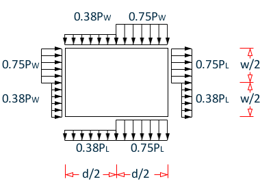
in Figure A-4.1.7.9. (1) are implemented. Regarding Case B, it is assumed that
only half of the building surface is loaded with indicated wind pressures (see
the following figure and note that h is the height of the surface.).
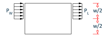
Generated
partial wind load cases NBC of Canada 2015
| Total Force = (PW + PL) (w/2)
h
| |
Similarly, it is assumed that partial
loads are applied to half surface for Case D:
Generated wind
load Case D of NBC of Canada 2015