| ASCE 7-10 / ASCE 7-05/ IBC 2006/2009 Equivalent
Lateral Force
|
| Setting | Description |
|---|
| Load Case |
States the Label of the load case being defined. |
| Load Case Provisions |
The provisions for calculating seismic forces vary depending on whether the generated forces are to be used for the calculation of drift, member forces or foundation forces. Load cases can be defined for each provision, allowing for the simultaneous investigation of the three conditions. See building code for more information. |
| Direction |
Use the Direction box to indicate the direction of the force (X, Y, or both) by clicking on the corresponding box so that the box is marked. One load case will be generated for each direction at which the force acts. |
| Eccentricity |
You may choose to include the effects of accidental torsion in the application of the seismic forces. The value of eccentricity used is specified in Loads - Masses. A default value of 5% is assumed by the program. See building code for more information. |
| Structural Period |
This is the period of the building which can be obtained through eigenvalue analysis or through the specified code equations. See building code for more information. |
| R |
The response modification coefficient is defined by and specified in the appropriate code. See building code for more information. |
| Seismic Design Category |
The Seismic Design Category is specified in IBC Table 1613.5.6(1) and Table 1613.5.6(2). It is based on the Occupancy Category, SDS, and SD1 and can be determined directly from the user input. You can either designate that the program determine the Seismic Design Category or else enter it directly; this is only necessary if you want to over-ride what the program would otherwise select. |
| Occupancy Category
|
Occupancy Category determined according to IBC
Table 1604.5.
|
| Site Class |
The Site Class is specified in IBC Table 1613.5.5. It is based on the Soil profile and properties. |
| Ss |
Ss is the mapped spectral accelerations for short periods as determined in IBC Section 1613.5.1. Values are given in Figures 1613.5(1) through 1613.5(14) |
| S1 |
S1 is the mapped spectral accelerations for a 1-second period as determined in IBC Section 1613.5.1. Values are given in Figures 1613.5(1) through 1613.5(14) |
| TL |
Long-period transition period(s) given in Figures from 22-15 to 22-20 in ASCE 7-05. |
| Importance Factor |
The Importance Factor is defined by and specified in the appropriate code. See the building code for more information. |
| Generate Additional Load Cases for Analysis with Tension-Only Members |
RAM Frame utilizes a nonlinear analysis algorithm to keep track of tension-only members during solution of the structural model under applied loads. Since the process has a nonlinear (iterative) nature, analysis results can not be simply superposed with other results as in load combination option in RAM Frame. Therefore, each lateral load case (wind or seismic) are solved separately.
Since the direction of the lateral loads become important in an iterative analysis, RAM Frame provides an option such that additional load cases can be created upon user request. When Generate Additional Load Cases for Analysis with Tension-Only Members in generating lateral load cases (wind and seismic load cases only) is invoked, additional load cases are created. For instance, there are 12 load cases generated for a regular IBC 2000 (ASCE 7-98) Wind load case. If this box is checked, the number of the load cases becomes 22. Additional load cases are created to account for directional effects of applied loads so that the most severe loading case is captured.

Conceptual example of additional load cases for tension-only members
|
| Orthogonal Effects (100/30) |
Orthogonal load cases can be created based on the 100%/30% requirement of some building codes: loads are applied 100% in one direction and 30% in the orthogonal direction at the same time. This is only implemented for US seismic load cases. To invoke this feature, select the Consider Orthogonal Effects (100/30) option when generating seismic load cases. Note that invoking this option substantially increases the number of load cases created. For instance, a total of 36 different load cases (40 if Generate Additional Load Cases for Analysis with Tension-Only Members is also checked) are created for IBC 2000 seismic load case. The following figure shows an example of the generated load cases.
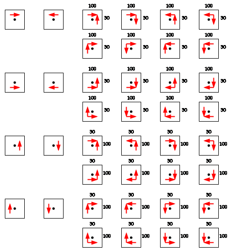
Generated load cases based on 100%/30% rule and additional cases for tension-only members
|
|
| ASCE 7-02/IBC 2003 Equivalent Lateral Force
|
| Setting | Description |
|---|
| Load Case |
States the Label of the load case being defined. |
| Load Case Provisions |
The provisions for calculating seismic forces vary depending on whether the generated forces are to be used for the calculation of drift, member forces or foundation forces. Load cases can be defined for each provision, allowing for the simultaneous investigation of the three conditions. See building code for more information. |
| Direction |
Use the Direction box to indicate the direction of the force (X, Y, or both) by clicking on the corresponding box so that the box is marked. One load case will be generated for each direction at which the force acts. |
| Eccentricity |
You may choose to include the effects of accidental torsion in the application of the seismic forces. The value of eccentricity used is specified in Loads - Masses. A default value of 5% is assumed by the program. See building code for more information. |
| Structural Period |
This is the period of the building which can be obtained through eigenvalue analysis or through the specified code equations. See building code for more information. |
| R |
The response modification coefficient is defined by and specified in the appropriate code. See building code for more information. |
| Seismic Design Category |
The Seismic Design Category is specified in IBC Table 1613.5.6(1) and Table 1613.5.6(2). It is based on the Occupancy Category, SDS, and SD1 and can be determined directly from the user input. You can either designate that the program determine the Seismic Design Category or else enter it directly; this is only necessary if you want to over-ride what the program would otherwise select. |
| Site Class |
The Site Class is specified in IBC Table 1615.1.1. It is based on the Soil profile and properties. |
| Ss |
Ss is the mapped spectral accelerations for short periods as determined in IBC Section 1615.1. Values are given in Figures 1615(1) through 1615(10). |
| S1 |
S1 is the mapped spectral accelerations for a 1-second period as determined in IBC Section 1615.1. Values are given in Figures 1615(1) through 1615(10). |
| Importance Factor |
The Importance Factor is defined by and specified in the appropriate code. See the building code for more information. |
| Generate Additional Load Cases for Analysis with Tension-Only Members |
RAM Frame utilizes a nonlinear analysis algorithm to keep track of tension-only members during solution of the structural model under applied loads. Since the process has a nonlinear (iterative) nature, analysis results can not be simply superposed with other results as in load combination option in RAM Frame. Therefore, each lateral load case (wind or seismic) are solved separately.
Since the direction of the lateral loads become important in an iterative analysis, RAM Frame provides an option such that additional load cases can be created upon user request. When Generate Additional Load Cases for Analysis with Tension-Only Members in generating lateral load cases (wind and seismic load cases only) is invoked, additional load cases are created. For instance, there are 12 load cases generated for a regular IBC 2000 (ASCE 7-98) Wind load case. If this box is checked, the number of the load cases becomes 22. Additional load cases are created to account for directional effects of applied loads so that the most severe loading case is captured.
Conceptual example of additional load cases for tension-only members
|
| Orthogonal Effects (100/30) |
Orthogonal load cases can be created based on the 100%/30% requirement of some building codes: loads are applied 100% in one direction and 30% in the orthogonal direction at the same time. This is only implemented for US seismic load cases. To invoke this feature, select the Consider Orthogonal Effects (100/30) option when generating seismic load cases. Note that invoking this option substantially increases the number of load cases created. For instance, a total of 36 different load cases (40 if Generate Additional Load Cases for Analysis with Tension-Only Members is also checked) are created for IBC 2000 seismic load case. The following figure shows an example of the generated load cases.
Generated load cases based on 100%/30% rule and additional cases for tension-only members
|
|
| IBC 2000 Equivalent Lateral Force
|
| Setting | Description |
|---|
| Load Case |
States the Label of the load case being defined. |
| Load Case Provisions |
The provisions for calculating seismic forces vary depending on whether the generated forces are to be used for the calculation of drift, member forces or foundation forces. Load cases can be defined for each provision, allowing for the simultaneous investigation of the three conditions. See building code for more information. |
| Direction |
Use the Direction box to indicate the direction of the force (X, Y, or both) by clicking on the corresponding box so that the box is marked. One load case will be generated for each direction at which the force acts. |
| Eccentricity |
You may choose to include the effects of accidental torsion in the application of the seismic forces. The value of eccentricity used is specified in Loads - Masses. A default value of 5% is assumed by the program. See building code for more information. |
| Structural Period |
This is the period of the building which can be obtained through eigenvalue analysis or through the specified code equations. See building code for more information. |
| R |
The response modification coefficient is defined by and specified in the appropriate code. See building code for more information. |
| Seismic Design Category |
The Seismic Design Category is specified in IBC Table 1613.5.6(1) and Table 1613.5.6(2). It is based on the Occupancy Category, SDS, and SD1 and can be determined directly from the user input. You can either designate that the program determine the Seismic Design Category or else enter it directly; this is only necessary if you want to over-ride what the program would otherwise select. |
| Site Class |
The Site Class is specified in IBC Table 1615.1.1. It is based on the Soil profile and properties. |
| Ss
|
Ss is the mapped spectral accelerations for
short periods as determined in IBC Section 1615.1. Values are given in Figures
1615(1) through 1615(10).
|
| S1
|
S1 is the mapped spectral accelerations for a
1-second period as determined in IBC Section 1615.1. Values are given in
Figures 1615(1) through 1615(10).
|
| Importance Factor |
The Importance Factor is defined by and specified in the appropriate code. See the building code for more information. |
| Generate Additional Load Cases for Analysis with Tension-Only Members |
RAM Frame utilizes a nonlinear analysis algorithm to keep track of tension-only members during solution of the structural model under applied loads. Since the process has a nonlinear (iterative) nature, analysis results can not be simply superposed with other results as in load combination option in RAM Frame. Therefore, each lateral load case (wind or seismic) are solved separately.
Since the direction of the lateral loads become important in an iterative analysis, RAM Frame provides an option such that additional load cases can be created upon user request. When Generate Additional Load Cases for Analysis with Tension-Only Members in generating lateral load cases (wind and seismic load cases only) is invoked, additional load cases are created. For instance, there are 12 load cases generated for a regular IBC 2000 (ASCE 7-98) Wind load case. If this box is checked, the number of the load cases becomes 22. Additional load cases are created to account for directional effects of applied loads so that the most severe loading case is captured.
Conceptual example of additional load cases for tension-only members
|
| Orthogonal Effects (100/30) |
Orthogonal load cases can be created based on the 100%/30% requirement of some building codes: loads are applied 100% in one direction and 30% in the orthogonal direction at the same time. This is only implemented for US seismic load cases. To invoke this feature, select the Consider Orthogonal Effects (100/30) option when generating seismic load cases. Note that invoking this option substantially increases the number of load cases created. For instance, a total of 36 different load cases (40 if Generate Additional Load Cases for Analysis with Tension-Only Members is also checked) are created for IBC 2000 seismic load case. The following figure shows an example of the generated load cases.
Generated load cases based on 100%/30% rule and additional cases for tension-only members
|
|
| UBC 94/97 Seismic Static Force Procedure
|
| Setting | Description |
|---|
| Load Case |
States the Label of the load case being defined. |
| Direction |
Use the Direction box to indicate the direction of the force (X, Y, or both) by clicking on the corresponding box so that the box is marked. One load case will be generated for each direction at which the force acts. |
| Eccentricity |
You may choose to include the effects of accidental torsion in the application of the seismic forces. The value of eccentricity used is specified in Loads - Masses. A default value of 5% is assumed by the program. See building code for more information. |
| Structural Period |
This is the period of the building which can be obtained through eigenvalue analysis or through the specified code equations. See building code for more information. |
| Zone
|
The seismic zone that the building is located
in. This is used to determine which special seismic provisions in the UBC are
applicable to the
frame types
designated.
|
| R |
The response modification coefficient is defined by and specified in the appropriate code. See building code for more information. |
| Soil |
The Soil Profile Type is defined by and specified in the appropriate code. See the building code for more information. |
| Importance Factor |
The Importance Factor is defined by and specified in the appropriate code. See the building code for more information. |
| Load Case Provisions |
The provisions for calculating seismic forces vary depending on whether the generated forces are to be used for the calculation of drift, member forces or foundation forces. Load cases can be defined for each provision, allowing for the simultaneous investigation of the three conditions. See building code for more information. |
| Generate Additional Load Cases for Analysis with Tension-Only Members |
RAM Frame utilizes a nonlinear analysis algorithm to keep track of tension-only members during solution of the structural model under applied loads. Since the process has a nonlinear (iterative) nature, analysis results can not be simply superposed with other results as in load combination option in RAM Frame. Therefore, each lateral load case (wind or seismic) are solved separately.
Since the direction of the lateral loads become important in an iterative analysis, RAM Frame provides an option such that additional load cases can be created upon user request. When Generate Additional Load Cases for Analysis with Tension-Only Members in generating lateral load cases (wind and seismic load cases only) is invoked, additional load cases are created. For instance, there are 12 load cases generated for a regular IBC 2000 (ASCE 7-98) Wind load case. If this box is checked, the number of the load cases becomes 22. Additional load cases are created to account for directional effects of applied loads so that the most severe loading case is captured.
Conceptual example of additional load cases for tension-only members
|
| Orthogonal Effects (100/30) |
Orthogonal load cases can be created based on the 100%/30% requirement of some building codes: loads are applied 100% in one direction and 30% in the orthogonal direction at the same time. This is only implemented for US seismic load cases. To invoke this feature, select the Consider Orthogonal Effects (100/30) option when generating seismic load cases. Note that invoking this option substantially increases the number of load cases created. For instance, a total of 36 different load cases (40 if Generate Additional Load Cases for Analysis with Tension-Only Members is also checked) are created for IBC 2000 seismic load case. The following figure shows an example of the generated load cases.
Generated load cases based on 100%/30% rule and additional cases for tension-only members
|
|
| Eurocode ENV1998-1-1:199
|
| Setting | Description |
|---|
| Load Case |
States the Label of the load case being defined. |
| Direction |
Use the Direction box to indicate the direction of the force (X, Y, or both) by clicking on the corresponding box so that the box is marked. One load case will be generated for each direction at which the force acts. |
| Eccentricity |
You may choose to include the effects of accidental torsion in the application of the seismic forces. The value of eccentricity used is specified in Loads - Masses. A default value of 5% is assumed by the program. See building code for more information. |
| Structural Period |
This is the period of the building which can be obtained through eigenvalue analysis or through the specified code equations. See building code for more information. |
| Distribution Method
|
The generated base shear can be distributed
up the height of the structure based on either the fundamental mode shape or
relative to story height and mass (linear). Refer to the Eurocode
ENV1998-1-1:1994 for more information on story shear distribution.
|
| Behavior Factor
|
The response spectra from which the base shear
is determined is modified to account for the material ductility which is
represented by the Behavior Factor (q). Refer to the Eurocode ENV1998-1-1:1994
for additional information concerning the Behavior Factor.
|
| Soil |
The Soil Profile Type is defined by and specified in the appropriate code. See the building code for more information. |
| Generate Additional Load Cases for Analysis with Tension-Only Members |
RAM Frame utilizes a nonlinear analysis algorithm to keep track of tension-only members during solution of the structural model under applied loads. Since the process has a nonlinear (iterative) nature, analysis results can not be simply superposed with other results as in load combination option in RAM Frame. Therefore, each lateral load case (wind or seismic) are solved separately.
Since the direction of the lateral loads become important in an iterative analysis, RAM Frame provides an option such that additional load cases can be created upon user request. When Generate Additional Load Cases for Analysis with Tension-Only Members in generating lateral load cases (wind and seismic load cases only) is invoked, additional load cases are created. For instance, there are 12 load cases generated for a regular IBC 2000 (ASCE 7-98) Wind load case. If this box is checked, the number of the load cases becomes 22. Additional load cases are created to account for directional effects of applied loads so that the most severe loading case is captured.
Conceptual example of additional load cases for tension-only members
|
|
| NBCC-95 Seismic
|
| Setting | Description |
|---|
| Load Case |
States the Label of the load case being defined. |
| Direction |
Use the Direction box to indicate the direction of the force (X, Y, or both) by clicking on the corresponding box so that the box is marked. One load case will be generated for each direction at which the force acts. |
| Eccentricity |
You may choose to include the effects of accidental torsion in the application of the seismic forces. The value of eccentricity used is specified in Loads - Masses. A default value of 5% is assumed by the program. See building code for more information. |
| Structural Period |
This is the period of the building which can be obtained through eigenvalue analysis or through the specified code equations. See building code for more information. |
| Force Modification Factor, R
|
The Force Modification Factor is defined and
specified by NBCC-95. It is given in table 4.1.9.1.B and ranges from 1 to 4
with typical values of 3 or 4.
|
| Seismic Importance Factor, I
|
The Seismic Importance Factor is defined and
specified by the code.
|
| Foundation Factor
|
The Foundation Factor is defined and specified
by the NBCC-95 and is given in table 4.1.9.1.C. Values for the Foundation
Factor range from 1.0 to 2.0.
|
| Seismic Zones
|
| Setting | Description |
|---|
| Za
|
acceleration related seismic zone as
specified in NBCC-95.
|
| Zv
|
velocity related seismic zone as
specified in NBCC-95.
|
|
| Generate Additional Load Cases for Analysis with Tension-Only Members |
RAM Frame utilizes a nonlinear analysis algorithm to keep track of tension-only members during solution of the structural model under applied loads. Since the process has a nonlinear (iterative) nature, analysis results can not be simply superposed with other results as in load combination option in RAM Frame. Therefore, each lateral load case (wind or seismic) are solved separately.
Since the direction of the lateral loads become important in an iterative analysis, RAM Frame provides an option such that additional load cases can be created upon user request. When Generate Additional Load Cases for Analysis with Tension-Only Members in generating lateral load cases (wind and seismic load cases only) is invoked, additional load cases are created. For instance, there are 12 load cases generated for a regular IBC 2000 (ASCE 7-98) Wind load case. If this box is checked, the number of the load cases becomes 22. Additional load cases are created to account for directional effects of applied loads so that the most severe loading case is captured.
Conceptual example of additional load cases for tension-only members
|
|
| NBCC-2005 Seismic
|
| Setting | Description |
|---|
| Load Case |
States the Label of the load case being defined. |
| Direction |
Use the Direction box to indicate the direction of the force (X, Y, or both) by clicking on the corresponding box so that the box is marked. One load case will be generated for each direction at which the force acts. |
| Eccentricity |
You may choose to include the effects of accidental torsion in the application of the seismic forces. The value of eccentricity used is specified in Loads - Masses. A default value of 5% is assumed by the program. See building code for more information. |
| Force Modification Factors
|
The following must be provided for both X-Dir
and Y-Dir:
| Setting | Description |
|---|
| Rd
|
Ductility related force modification factor, Rd, reflecting the capability of a structure to dissipate energy through inelastic behavior is required from the user for each direction. This factor is provided in Table 4.1.8.9.
|
| Ro
|
Overstrength related force modification factor, Ro, accounting for the dependable portion of reserve strength in a structure is required from the user for each direction. This factor is provided in Table 4.1.8.9.
|
|
| Structural Period
|
The fundamental period (Ta) is based on one of the following choices:
Note that hn is height of the building (in meters). In above equations, all options are implemented in the program except 0.1N. Instead, you are always allowed to defined your own value for Tα. In addition, if required, the program calculates fundamental period from an Eigen analysis, and you are also provided a method to use this as well. The above equation is subjected to the following limits:
- For moment resisting frames: Tα ≤ 1.5 * that determined in Clause (a)
- For braced frames: Tα ≤ 2.0 * that determined in Clause (b)
- For Shear Wall Structures: Tα ≤ 2.0 * that determined in Clause (c)
Note that these upper limits specified above may not be checked for deflection/drift calculations. |
| Base Shear Adjustment Factor Due to Higher
Modes, Mv
|
This factor is read from Table 4.1.8.11, based on type of lateral resisting systems, Sa(0.2), Sa(2.0) and calculated value of Ta. You are required to choose lateral resisting system for each direction.
|
| Importance Factor, I
|
It is given in Table 4.1.8.5
|
| Load Directions
|
Four load cases are generated as follows:

Generated Load Cases for NBC of Canada 2005 Seismic
100%/30% orthogonal loading is implemented in the software as referenced in 4.1.8.8. |
| Generate Additional Load Cases for Analysis with Tension-Only Members |
RAM Frame utilizes a nonlinear analysis algorithm to keep track of tension-only members during solution of the structural model under applied loads. Since the process has a nonlinear (iterative) nature, analysis results can not be simply superposed with other results as in load combination option in RAM Frame. Therefore, each lateral load case (wind or seismic) are solved separately.
Since the direction of the lateral loads become important in an iterative analysis, RAM Frame provides an option such that additional load cases can be created upon user request. When Generate Additional Load Cases for Analysis with Tension-Only Members in generating lateral load cases (wind and seismic load cases only) is invoked, additional load cases are created. For instance, there are 12 load cases generated for a regular IBC 2000 (ASCE 7-98) Wind load case. If this box is checked, the number of the load cases becomes 22. Additional load cases are created to account for directional effects of applied loads so that the most severe loading case is captured.
Conceptual example of additional load cases for tension-only members
|
|
| NBCC-2015 Seismic
|
| Setting | Description |
|---|
| Load Case |
States the Label of the load case being defined. |
| Direction |
Use the Direction box to indicate the direction of the force (X, Y, or both) by clicking on the corresponding box so that the box is marked. One load case will be generated for each direction at which the force acts. |
| Eccentricity |
You may choose to include the effects of accidental torsion in the application of the seismic forces. The value of eccentricity used is specified in Loads - Masses. A default value of 5% is assumed by the program. See building code for more information. |
| Force Modification Factors
|
The following must be provided for both X-Dir
and Y-Dir:
| Setting | Description |
|---|
| Rd
|
Ductility related force modification factor, Rd, reflecting the capability of a structure to dissipate energy through inelastic behavior is required from the user for each direction. This factor is provided in Table 4.1.8.9.
|
| Ro
|
Overstrength related force modification factor, Ro, accounting for the dependable portion of reserve strength in a structure is required from the user for each direction. This factor is provided in Table 4.1.8.9.
|
|
| Base Shear Adjustment Factor Due to Higher
Modes, Mv
|
This factor is read from Table 4.1.8.11, based on type of lateral resisting systems, Sa(0.2), Sa(2.0) and calculated value of Ta. You are required to choose lateral resisting system for each direction.
|
| Structural Period
|
The fundamental period (Ta) is based on one of the following choices:
Note that hn is height of the building (in meters). In above equations, all options are implemented in the program except 0.1N. Instead, you are always allowed to defined your own value for Tα. In addition, if required, the program calculates fundamental period from an Eigen analysis, and you are also provided a method to use this as well. The above equation is subjected to the following limits:
- For moment resisting frames: Tα ≤ 1.5 * that determined in Clause (a)
- For braced frames: Tα ≤ 2.0 * that determined in Clause (b)
- For Shear Wall Structures: Tα ≤ 2.0 * that determined in Clause (c)
Note that these upper limits specified above may not be checked for deflection/drift calculations. |
| Importance Factor, I
|
It is given in Table 4.1.8.5
|
| Consider Orthogonal Effects (100%/30%)
|
Four load cases are generated as follows:
Generated Load Cases for NBC of Canada 2005 Seismic
100%/30% orthogonal loading is implemented in the software as referenced in 4.1.8.8. |
| Generate Additional Load Cases for Analysis with Tension-Only Members |
RAM Frame utilizes a nonlinear analysis algorithm to keep track of tension-only members during solution of the structural model under applied loads. Since the process has a nonlinear (iterative) nature, analysis results can not be simply superposed with other results as in load combination option in RAM Frame. Therefore, each lateral load case (wind or seismic) are solved separately.
Since the direction of the lateral loads become important in an iterative analysis, RAM Frame provides an option such that additional load cases can be created upon user request. When Generate Additional Load Cases for Analysis with Tension-Only Members in generating lateral load cases (wind and seismic load cases only) is invoked, additional load cases are created. For instance, there are 12 load cases generated for a regular IBC 2000 (ASCE 7-98) Wind load case. If this box is checked, the number of the load cases becomes 22. Additional load cases are created to account for directional effects of applied loads so that the most severe loading case is captured.
Conceptual example of additional load cases for tension-only members
|
|
| China GB50011-2001
|
| Setting | Description |
|---|
| Load Case |
States the Label of the load case being defined. |
| Direction |
Use the Direction box to indicate the direction of the force (X, Y, or both) by clicking on the corresponding box so that the box is marked. One load case will be generated for each direction at which the force acts. |
| Eccentricity |
You may choose to include the effects of accidental torsion in the application of the seismic forces. The value of eccentricity used is specified in Loads - Masses. A default value of 5% is assumed by the program. See building code for more information. |
| Structure Period |
Structure periods can be automatically calculated by the program for both X and Y direction (note that the program considers period that is based on the Eigen mode (i.e., mode shape) with highest building mass participation). Or, the user can enter structure period for X and Y direction separately. Note that if the 1st option is chosen (Use Calculated T), then the period multiplier is directly applied to calculated period (by default, it is 1.0). |
| Additional Seismic Action Factor
|
Additional seismic action factor,
δn, is defined at the top of the
building and thus, an additional force, ΔFn, is
applied at the top:
where | FEK
| = | the building base
shear |
The following options are provided to calculate δn:
- it is not considered (i.e., ΔFn =0)
- δn is provided by the engineer
- it is directly read from the Table 5.2.1 of GB50011-2001.
|
| Earthquake Group |
The following earthquake groups are available: 1, 2 and 3. |
| Earthquake Type |
The following earthquake types are available : Frequent and Rare |
| Soil Site Class |
The following soil site class are available: I, II, III, and IV |
| Fortification Intensity |
The following fortification intensities are available: 6, 7, 7(0.15g), 8, 8(0.30g) and 9. Values with parenthesis are used for design basic acceleration of ground motion with 0.15g and 0.30g. |
| Base Shear Scale Factors
|
These factors are directly applied to
calculated building seismic base shears in both X and Y directions.
|
| Generate Additional Load Cases for Analysis with Tension-Only Members |
RAM Frame utilizes a nonlinear analysis algorithm to keep track of tension-only members during solution of the structural model under applied loads. Since the process has a nonlinear (iterative) nature, analysis results can not be simply superposed with other results as in load combination option in RAM Frame. Therefore, each lateral load case (wind or seismic) are solved separately.
Since the direction of the lateral loads become important in an iterative analysis, RAM Frame provides an option such that additional load cases can be created upon user request. When Generate Additional Load Cases for Analysis with Tension-Only Members in generating lateral load cases (wind and seismic load cases only) is invoked, additional load cases are created. For instance, there are 12 load cases generated for a regular IBC 2000 (ASCE 7-98) Wind load case. If this box is checked, the number of the load cases becomes 22. Additional load cases are created to account for directional effects of applied loads so that the most severe loading case is captured.
Conceptual example of additional load cases for tension-only members
|
|
| AS 1170.4-2007
|
| Setting | Description |
|---|
| Load Case |
States the Label of the load case being defined. |
| Direction |
Use the Direction box to indicate the direction of the force (X, Y, or both) by clicking on the corresponding box so that the box is marked. One load case will be generated for each direction at which the force acts. |
| Eccentricity |
You may choose to include the effects of accidental torsion in the application of the seismic forces. The value of eccentricity used is specified in Loads - Masses. A default value of 5% is assumed by the program. See building code for more information. |
| Structure Period
|
Three options are provided to user for natural period of structure in X- and Y-directions:
- Either it is directly calculated by the program
- Or it is directly provided by user
- Or it is calculated according to Eq. 6.2(7):
where kt is defined as follows:
| Frame Type |
kt |
| Moment-resisting steel frames |
0.11 |
| Moment-resisting concrete frames |
0.075 |
| Eccentrically braced steel frames |
0.06 |
| All other structures |
0.05 |
The base shear obtained using either calculated by the program or user entered shall not be less than 80% of the value obtained with T1 according to above equation. Thus, the user needs to enter kt for each direction for fulfilling this requirement. This check is enforced in the program.
|
| Building Seismic Properties group |
Type values for both X and Y directions. | Setting | Description |
|---|
| Structural Ductility Factor (mu) |
µ; Refer to Section 6.5 of the building code |
| Structural Performance Factor (Sp) |
Refer to Section 6.5 of the building code |
|
| Site Hazard Factors |
| Setting | Description |
|---|
| Probability Factor (kp) |
Refer to Section 3, Table 3.1 of the building code |
| Hazard Factor (Z) |
Refer to Section 3, Table 3.2 of the building code |
|
| Site Sub-soil Class |
Select one of the five different site sub-soil class: Ae. Be, Ce, De, or Ee |
| Generate Additional Load Cases for Analysis with Tension-Only Members |
RAM Frame utilizes a nonlinear analysis algorithm to keep track of tension-only members during solution of the structural model under applied loads. Since the process has a nonlinear (iterative) nature, analysis results can not be simply superposed with other results as in load combination option in RAM Frame. Therefore, each lateral load case (wind or seismic) are solved separately.
Since the direction of the lateral loads become important in an iterative analysis, RAM Frame provides an option such that additional load cases can be created upon user request. When Generate Additional Load Cases for Analysis with Tension-Only Members in generating lateral load cases (wind and seismic load cases only) is invoked, additional load cases are created. For instance, there are 12 load cases generated for a regular IBC 2000 (ASCE 7-98) Wind load case. If this box is checked, the number of the load cases becomes 22. Additional load cases are created to account for directional effects of applied loads so that the most severe loading case is captured.
Conceptual example of additional load cases for tension-only members
|
| Orthogonal Effects (100/30) |
Orthogonal load cases can be created based on the 100%/30% requirement of some building codes: loads are applied 100% in one direction and 30% in the orthogonal direction at the same time. This is only implemented for US seismic load cases. To invoke this feature, select the Consider Orthogonal Effects (100/30) option when generating seismic load cases. Note that invoking this option substantially increases the number of load cases created. For instance, a total of 36 different load cases (40 if Generate Additional Load Cases for Analysis with Tension-Only Members is also checked) are created for IBC 2000 seismic load case. The following figure shows an example of the generated load cases.
Generated load cases based on 100%/30% rule and additional cases for tension-only members
|
|
| IS 1893 (Part1): 2002, 5th Rev. / 2016, 6th Rev.
|
| Setting | Description |
|---|
| Load Case |
States the Label of the load case being defined. |
| Direction |
Use the Direction box to indicate the direction of the force (X, Y, or both) by clicking on the corresponding box so that the box is marked. One load case will be generated for each direction at which the force acts. |
| Eccentricity |
You may choose to include the effects of accidental torsion in the application of the seismic forces. The value of eccentricity used is specified in Loads - Masses. A default value of 5% is assumed by the program. See building code for more information. |
| Structural Period |
This is the period of the building which can be obtained through eigenvalue analysis or through the specified code equations. See building code for more information. |
| R |
The response modification coefficient is defined by and specified in the appropriate code. See building code for more information. |
| Soil Site Type
|
Select the applicable soil description.
- Type I (Rocky
or Hard Soil)
- Type II
(Medium Soil)
- Type III (Soft
Soil)
|
| Seismic Zone Factor
|
Select the seismic intensity from the list.
|
| Importance Factor |
The Importance Factor is defined by and specified in the appropriate code. See the building code for more information. |
| Damping
|
(2002, 5th Rev only) Specify a damping ratio
which is used to modify the the Sa/g values.
|
| Orthogonal Effects (100/30) |
Orthogonal load cases can be created based on the 100%/30% requirement of some building codes: loads are applied 100% in one direction and 30% in the orthogonal direction at the same time. This is only implemented for US seismic load cases. To invoke this feature, select the Consider Orthogonal Effects (100/30) option when generating seismic load cases. Note that invoking this option substantially increases the number of load cases created. For instance, a total of 36 different load cases (40 if Generate Additional Load Cases for Analysis with Tension-Only Members is also checked) are created for IBC 2000 seismic load case. The following figure shows an example of the generated load cases.
Generated load cases based on 100%/30% rule and additional cases for tension-only members
|
| Generate Additional Load Cases for Analysis with Tension-Only Members |
RAM Frame utilizes a nonlinear analysis algorithm to keep track of tension-only members during solution of the structural model under applied loads. Since the process has a nonlinear (iterative) nature, analysis results can not be simply superposed with other results as in load combination option in RAM Frame. Therefore, each lateral load case (wind or seismic) are solved separately.
Since the direction of the lateral loads become important in an iterative analysis, RAM Frame provides an option such that additional load cases can be created upon user request. When Generate Additional Load Cases for Analysis with Tension-Only Members in generating lateral load cases (wind and seismic load cases only) is invoked, additional load cases are created. For instance, there are 12 load cases generated for a regular IBC 2000 (ASCE 7-98) Wind load case. If this box is checked, the number of the load cases becomes 22. Additional load cases are created to account for directional effects of applied loads so that the most severe loading case is captured.
Conceptual example of additional load cases for tension-only members
|
|
| All Other Building Codes
|
| Setting | Description |
|---|
| Load Case |
States the Label of the load case being defined. |
| Load Case Provisions |
The provisions for calculating seismic forces vary depending on whether the generated forces are to be used for the calculation of drift, member forces or foundation forces. Load cases can be defined for each provision, allowing for the simultaneous investigation of the three conditions. See building code for more information. |
| Direction |
Use the Direction box to indicate the direction of the force (X, Y, or both) by clicking on the corresponding box so that the box is marked. One load case will be generated for each direction at which the force acts. |
| Eccentricity |
You may choose to include the effects of accidental torsion in the application of the seismic forces. The value of eccentricity used is specified in Loads - Masses. A default value of 5% is assumed by the program. See building code for more information. |
| Structural Period |
This is the period of the building which can be obtained through eigenvalue analysis or through the specified code equations. See building code for more information. |
| R |
The response modification coefficient is defined by and specified in the appropriate code. See building code for more information. |
| Soil |
The Soil Profile Type is defined by and specified in the appropriate code. See the building code for more information. |
| Av
|
The seismic coefficient representing the
effective peak velocity. See the building code for more information.
|
| Aa
|
The seismic coefficient representing the
effective peak acceleration. See the building code for more information.
|
| Generate Additional Load Cases for Analysis with Tension-Only Members |
RAM Frame utilizes a nonlinear analysis algorithm to keep track of tension-only members during solution of the structural model under applied loads. Since the process has a nonlinear (iterative) nature, analysis results can not be simply superposed with other results as in load combination option in RAM Frame. Therefore, each lateral load case (wind or seismic) are solved separately.
Since the direction of the lateral loads become important in an iterative analysis, RAM Frame provides an option such that additional load cases can be created upon user request. When Generate Additional Load Cases for Analysis with Tension-Only Members in generating lateral load cases (wind and seismic load cases only) is invoked, additional load cases are created. For instance, there are 12 load cases generated for a regular IBC 2000 (ASCE 7-98) Wind load case. If this box is checked, the number of the load cases becomes 22. Additional load cases are created to account for directional effects of applied loads so that the most severe loading case is captured.
Conceptual example of additional load cases for tension-only members
|
| Orthogonal Effects (100/30) |
Orthogonal load cases can be created based on the 100%/30% requirement of some building codes: loads are applied 100% in one direction and 30% in the orthogonal direction at the same time. This is only implemented for US seismic load cases. To invoke this feature, select the Consider Orthogonal Effects (100/30) option when generating seismic load cases. Note that invoking this option substantially increases the number of load cases created. For instance, a total of 36 different load cases (40 if Generate Additional Load Cases for Analysis with Tension-Only Members is also checked) are created for IBC 2000 seismic load case. The following figure shows an example of the generated load cases.
Generated load cases based on 100%/30% rule and additional cases for tension-only members
|
|