Analytical Modeling Details
When a SidePlate® connection is assigned to a lateral beam, the program applies the following steps:
- A beam rigid end zone is always defined irrespective of Rigid End Zone option given in the Criteria dialog. In other words, the program always inserts a rigid end zone link between the beam and the column even though Rigid End Zone option in the Criteria dialog is not invoked. This link is infinitely rigid for bending and axial. The link starts from the centerline of the column and its length is determined based on column orientation.
- A column rigid end zone is always defined for the column framing into the beam with SidePlate connection. This is carried out irrespective of Rigid End Zone option given in the Criteria dialog. It should be noted that rigid end zone is created only for top end of column and its length is determined as follows:
- Number of analytical zones
created for a
SidePlate
connection is determined
according to
SidePlate
connection type. If
selected type is
Moment Frame – Filed Bolted (R=3), the program
does only include rigid link zone. For other types, the program creates the
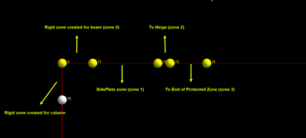
following (analytical) zones:
- Zone 0: this is rigid link zone and it is infinitely rigid for bending and axial.
- Zone 1: SidePlate section (from face-of-column to end-of- SidePlate ). The length and stiffness properties of this zone are based on beam size and other proprietary information available in the SidePlate table.
- Zone 2: Hinge point location (from end-of- SidePlate to center-of-hinge). The length of this zone is based on proprietary information available in the SidePlate table. Beam stiffness properties are used for this zone.
- Zone 3: Protected zone location (from center-of-hinge to end-of-protected zone). The length of this zone is based on proprietary information available in the SidePlate table. Beam stiffness properties are used for this zone.
When analysis is started, the program checks beams with SidePlate connection assigned. If a beam has a bending release and SidePlate connection assigned at the same end of beam, the program ignores bending release condition for beam during analysis.