Equivalent Static Force Procedure is implemented according to Section 4.1.7, Division B of NBC 2005. The specified external pressure or suction (i.e., windward and leeward pressures) is calculated according to the following equation:
where
|
p
| = | external wind pressure, calculated in kN/m2 (kPa) |
Importance Factor for Wind Load (Iw)
It is given in table 4.1.7.1 and this parameter is expected to be provided by the user.
Reference Velocity Pressure ( q )
The reference velocity pressure is referenced in Sentence (4) of Section 4.1.7 and this parameter is expected to be provided by the user. Acceptable units are kN/m2 (kPa) psf or kg/m2.
Exposure Factor (Ce)
Exposure Factor can be determined based on one of the following three options (in calculations below, h is height above ground level, and it is defined in meters):
- Use provided value
- Static procedure: It is given in Sentence 4.1.7.1.(5)
- Open Terrain:
- Rough Terrain:
- Intermediate value between these two options (see Commentary I, pg. I-7, Paragraph 11). This is not implemented. Instead, the user is allowed to enter Ce
- Dynamic procedure: If dynamic approach to the action of wind gust is used, the exposure factor is refereed to Commentary I, pg. I-24, Paragraph 41 and it is calculated as follows:
- Exposure A: and 1.0 ≤ Ce ≤ 2.5
- Exposure B: and 0.5 ≤ Ce ≤ 2.5
- Exposure C: and 0.4 ≤ Ce ≤ 2.5
Gust Effect Factor (Gg)
Gust effect factor can be determined based on one of the following two options (in calculations below,
h is mean roof height in meters):
- Static procedure: Cg = 2.0
- Dynamic procedure: see Commentary I, pg. I-25, Paragraph 46-47
where
-
| = | -
|
-
gp
| = | - statistical peak factor for the loading effect
|
-
T
| = | -
3,600 s
|
-
v
| = | - average fluctuation rate
|
-
K
| = | - factor related to surface roughness
- = 0.08 for Exposure A
- = 0.10 for Exposure B
- = 0.14 for Exposure C
|
-
CeH
| = | - exposure factor at the top of the top of building (mean roof level). It is calculated according to dynamic procedure (Commentary I, p. I-24, Paragraph 41)
|
-
B
| = | - background turbulence factor obtained from Figure I-18 as a function of w/H (Commentary I, p. I-27), in which w is building width at a given height and H is mean roof height. Both are in meters.
|
-
s
| = | - size reduction factor obtained from Figure I-19 as a function of w/H (Commentary I, p. I-28) and reduced frequency,
|
-
fn
| = | - natural frequency of vibration for given direction (in Hz). It is either given by the user or computed by the program
|
-
VH
| = | - mean wind speed (m/s) at the top of the structure
|
-
| = | -
|
-
q
| = | - reference velocity pressure (kPa = kN/m2), which is provided by the user
|
-
F
| = | - gust energy ratio at the natural frequency of the structure obtained from Figure I-20 as a function of fn/vn
|
-
x0
| = | -
1,220 fn/VH
|
-
β
| = | - critical damping ratio in the along-wind direction
|
External Pressure Coefficient (Cp)
External pressure coefficients are calculated based on I-7 to I-14 and I-15. In the current implementation, the following is applied: for each direction, the user is given two options:
- Either Windward and Leeward Cp values are entered by the user
- Or it is calculated from Figure I-15 as follows (below H is the mean roof height and D is the depth of the building in the direction of the wind):
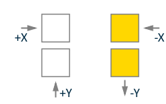
Loading Directions
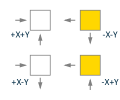
Loading directions Cases A-D as given in Figure I-16 are implemented. Regarding Case B, it is assumed that only half of the building surface is loaded with indicated wind pressures (see the following figure and note that h is the height of the surface.).

Generated partial wind load cases NBC of Canada 2005
| Total Force = (PW + PL) (w/2) h | |
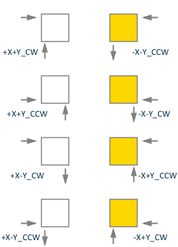
Similarly, it is assumed that partial loads are applied to half surface for Case D:

Generated wind load Case D of NBC of Canada 2005