Section Cuts
The Shear Wall Module works by reporting the forces on user-specified section cuts through walls. The section forces can be obtained graphically or through reports. When the program is launched from the RAM Frame Analysis Mode - Load Cases, then the results are for individual load cases. When the program is launched from the Load Combinations mode, then the section results are all given for the combinations.
The cursor will change into a cross-hair type cursor at this point.
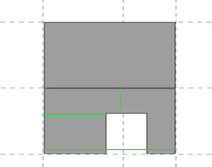
- Click and hold the mouse just left of the wall and drag the mouse horizontally through the entire length of the wall as pictured below.
When you let go of the cursor, an options box will pop up.
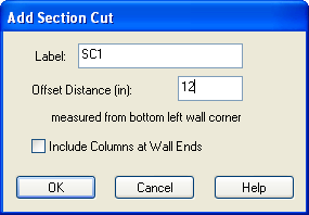
The Green section cut will be adjusted to be exactly 12" from the lowest left corner of the wall where the section cut started.
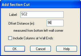
- Create a second section cut by dragging horizontally through the left part of the wall only, just below the top of the opening.
- Set the elevation of the section cut to 96 (2500) and click [OK].
- Now drag a slice vertically through the lintel near the middle of the opening, starting inside the opening and dragging up.
- For this cut the distance is measured relative to the corner of the opening (since the slice started in the opening). Set the offset distance to 24 (600) and click [OK].
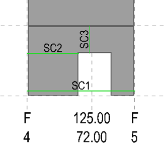
- To see the labels on the section cuts, select .
Once complete, the three completed cuts should look like the following figure.
To see the shear forces on the various section cuts:
- Select .
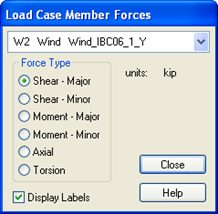
- In the options box that opens, select the first wind load case in the Y direction (Wind_IBC06_1_Y).
- For the Force Type select Shear – Major. At this point, the shear forces will appear on the graphic. If the text is too large or too small to read, it can be adjusted using the buttons to increase or decrease text size in the top menu bar.
- When finished, click [Close].
To see a table of the forces on an individual section:

A table of the section forces will appear. The forces are separated into axial forces P (positive = compression), overturning moment (Mmajor), out-of-plane moment (Mminor), shear along the length of the cut (Vmajor), shear perpendicular to the wall (Vminor) and torsion. For a wall with no included lateral columns, the minor axis shear and moment values (as well as torsion) will be zero since the walls are not assumed to have any significant out-of-plane stiffness in the analysis.