Coupling Beams
A coupling beam in the RAM Concrete Wall module is a region within a Wall Panel that is bounded above and below by one or more wall openings or Wall Panel edges. Coupling Beams must be created by the user. At the user's direction, Coupling Beams may be reinforced like beams. That is, they may contain top and bottom bars, side bars, and stirrups.
There are two primary motivations for the concept of a Coupling Beam within the program:
- They allow regions within walls that are dominated by flexural response, and thus act more like beams than Wall Panels, to be designed and detailed accordingly.
- They engage the prescriptions of the selected design code pertinent to headers and coupling beams for the respective region of the wall.
Unlike with Wall Panels, reinforcing cannot be chosen automatically by the program for Coupling Beams. They must be assigned either the global Coupling Beam reinforcing criteria, or given a custom reinforcing assignment using the tools within the View/Update dialog.
Coupling Beams are checked for in-plane shear and axial-flexural loads. Section Cut assignments are not necessary where Coupling Beams occur. Rather, the program internally and automatically creates Section Cuts within the Coupling Beam in order to perform the design checks. These Section Cuts are not displayed or exposed to the user in any way, other than for reporting the forces within critical locations of the Coupling Beam.
There is one notable difference between the Section Cuts created within Coupling Beams and vertical Section Cuts created by the user. When the user creates a vertical Section Cut that spans multiple stories, the program always creates a separate Section Cut at each story. With Coupling Beams however, a single Section Cut is used at each station, even when the Coupling Beam spans multiple stories.
Coupling Beams are checked for code prescriptive reinforcing limits. Among the basic checks considered are minimum and maximum longitudinal bar spacing, minimum and maximum longitudinal reinforcing ratio, and minimum and maximum transverse bar spacing. Basic member dimensional requirements are also checked where applicable, such as minimum wall thickness, span length, and height to length ratio.
The program follows the rule of placing a vertical Section Cut at the quarter points (0, 0.25L, 0.50L, 0.75L, and 1.00L) along the free spans of coupling beams (horizontal Section Cuts are not used within Coupling Beams). A free span is an extent along the Coupling Beam where an opening occurs both above and below. Each Section Cut is checked for in-plane shear and axial-flexural loads for all selected load combinations.
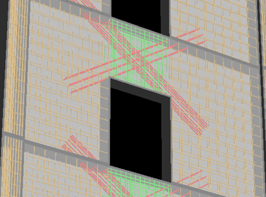
If supported by the design code in use, Coupling Beams may also include special diagonal reinforcement used in seismic applications. Currently, only ACI codes support the placement of diagonal reinforcement. This reinforcement consists of two column-like groups of longitudinal bars placed in a symmetric "X" configuration within the Coupling Beam. The user specifies the dimensions of each diagonal cage, and the size, number, and configuration of the longitudinal bars. The program then checks the strength and prescriptive reinforcement provisions considering the diagonal reinforcement in addition to the typical reinforcement.