DuraFuse Connection
DuraFuse® connections can be assigned to either or both ends of a lateral beam. If it is not assigned to an end, the Standard fixity assignment is used. This assignment can only be made to steel beams supported by steel columns. An error message is given if an attempt is made to assign it to beams of other material or to steel beams not supported by steel columns.
The program creates a special analytical model at the end of the beam where a DuraFuse connection is assigned. This includes creating special segments on the beam as well as on the column(s) connected to the beam. In addition, the program inserts a special panel zone element at the joint where the beam and column(s) are connected. Properties of DuraFuse connection are based on criteria selected in the . The program uses default values of connection parameters, but they can be overwritten in .
Analytical Model Details
The program creates a special analytical joint model at locations where DuraFuse® beam is framing into columns. This involves breaking up beams and columns into sub-elements with modified stiffness properties as well as inserting a special panel zone spring at the center of the joint. To create this type of analytical model, additional analysis nodes are created along the beams and columns.
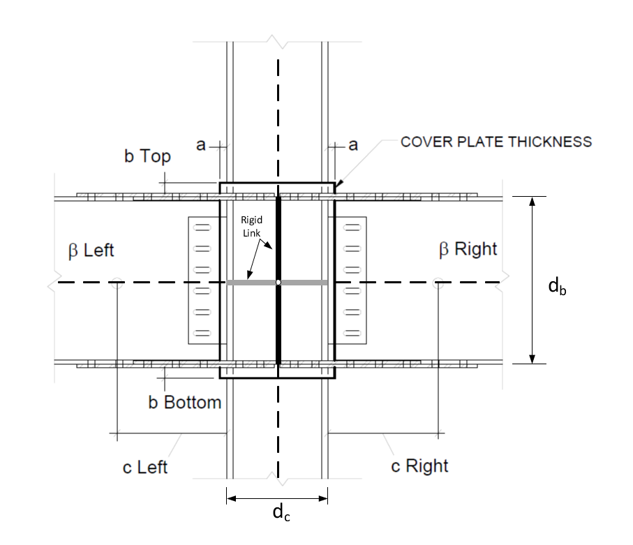
Referring to the figure above, the following steps are applied to create a DuraFuse® analytical model:
- A beam rigid end zone is always defined irrespective of Rigid End Zone option given in the Criteria dialog. In other words, the program always inserts a rigid end zone link between the beam and the column even though Rigid End Zone option in the Criteria dialog is not invoked. This link is infinitely rigid for bending and axial. The link starts from the centerline of the column, its length is 0.5dc (half of column depth) and it is extended into the beams on both sides of the joint.
- A column rigid end zone is
always defined for columns framing into the beam with DuraFuse ® connection.
This is carried out irrespective of Rigid End Zone option given in the
Criteria dialog. Note that the rigid end zone is
created for the top end of column that is supporting the DuraFuse ® beam. In
addition, for the column at story above and framing into the beam, the program
also creates a rigid end zone at the bottom end of the column.
Rigid end zone link is infinitely rigid for bending and axial, and it starts from centerline of beam. The length of the link is 0.5db (half of beam depth). In case of having different beam sizes at both side of the joint, the program uses the largest beam size in determining rigid link length.
-
The DuraFuse cover plate includes a side extension, dimension "a" on the figure above. By default, the length of the side extension "a" is 1 inch. This entry affects the calculation of the cover plate thickness and the stiffness calculated for the column in region b. See the command to modify the value of "a".
- The DuraFuse® beam member
includes a stiffened region, extended from the face of the column to a distance
of
"c", which is called the stiffened region (left or right). This
is marked with a symbol
"c" in the figure above. This region is not created if it is
defined as zero (i.e., regular beam stiffness properties are used for the
region if c = 0).
Stiffness property of the region can be controlled with a stiffness factor called β (see the figure). Note that the β factor is applied only to modify strong axis bending stiffness of beam element located within in the region "c". By default, c and β are 0.0 and 1.0, respectively. See the command to modify values of c and β.
- Column members of the DuraFuse® joint also include
a stiffened segment, which is called the top or bottom extension. The length of
this segment is marked with the symbol "b" (i.e., see bTop and bBottom in the figure). Stiffness property of this
segment is calculated from the following equations:
where
= - stiffness multiplier for column strong axis bending
= - stiffness multiplier for column weak axis bending
= - cover plate thickness (in or mm)
= - side extension or cover plate overhang (see the figure, in or mm)
= - strong axis column moment of inertia (in4 or mm4)
= - weak axis column moment of inertia (in4 or mm4)
= - column depth (in or mm)
= - column flange width (in or mm)
It is important to note that the stiffness factor is used to modify strong axis bending stiffness of the column element within the extension segment if a DuraFuse® beam is framing into the column flanges (i.e., column strong axis).
Similarly, the stiffness factor is applied to weak axis bending stiffness of column element located within the extension segment if there exists DuraFuse® beam framing into the column web (i.e., column weak axis).
By default, the length of the extension segment "b" is 3 inches. See the command to modify the value of "b".
Cover plate thickness, , is calculated as follows:
where= = = = = = - depth of beam (in case of having beams with different sizes at the joint, that of deeper two beams is used, in or mm)
= - thickness of beam flange (in case of having beams with different sizes at the joint, that of deeper two beams is used, in or mm)
= - depth of column (in or mm)
= - column flange thickness (in or mm)
= probable maximum force developed at the bottom flange of each side of the beams (kips or kN)
= - specified minimum yield stress of the cover plate (ksi or MPa, default value = 50 ksi)
= - thickness of top plates and fuse plate, typically equal to beam flange thickness tfb (if top and bottom flange have different thicknesses, the thicker flange used, in or mm)
= - side extension or cover plate overhang (see the figure, in or mm)
= - minimum specified yield strength of the beam (ksi or MPa)
Note: The program rounds the value calculated according to the equation above to the nearest standard plate size.You can also override the calculated value. Use the command.
- At the center of the
DuraFuse® joint, a special panel zone element is inserted. This special element
is represented with a rotational spring to account for panel zone shear
deformations. The scissors model is utilized to model panel zone area (further
information about the Scissors model is given below).
At the joint where a DuraFuse® beam framing into a column flange (i.e., column strong axis), a panel zone element is defined to capture shear deformations within panel zone area (a panel zone area is defined as the region composed of the column web and bounded by the extension of the beam flanges). In this case, panel zone spring stiffness is calculated as follows1:
where= - rotational spring constant of panel zone element (kips-in/rad or N-m/rad)
= - rotational spring stiffness due to panel (kips-in/rad or N-m/rad)
= - rotational spring stiffness due to column flanges (kips-in/rad or N-m/rad)
= = = = - depth of deeper beam framing into column flange (if beams have different sizes at both side of the joint, in or mm)
= - thickness of beam flange (in or mm)
= - depth of column (in or mm)
= - thickness of column flange (in or mm)
= - flange width of column (in or mm)
= - length of beam framing into column flange, measured from center-line-to-center line (longer span beam if there are beams at both side of the joint, in or mm)
= - story-to-story column height, measured from center-line-to-center line
= - volume of steel in the panel zone, computed as
= - shear modulus (ksi or MPa)
= - panel zone shear area (in2 or mm2), calculated as follows:
= - thickness of column web (in or mm)
= - cover plate thickness (in or mm)
= - side extension or cover plate overhang (in or mm)
If there is a DuraFuse® beam framing into a column weak axis, another panel zone element is inserted accordingly. This panel element is orthogonal to the panel zone element inserted for column strong axis direction. It is further assumed that these two panel zone elements are uncoupled, hence they act independently in their own planes. The same equations listed above applies for the weak axis except that panel zone shear area equation is updated as follows:
where= - column flange thickness (in or mm)
= - column flange width (in or mm)
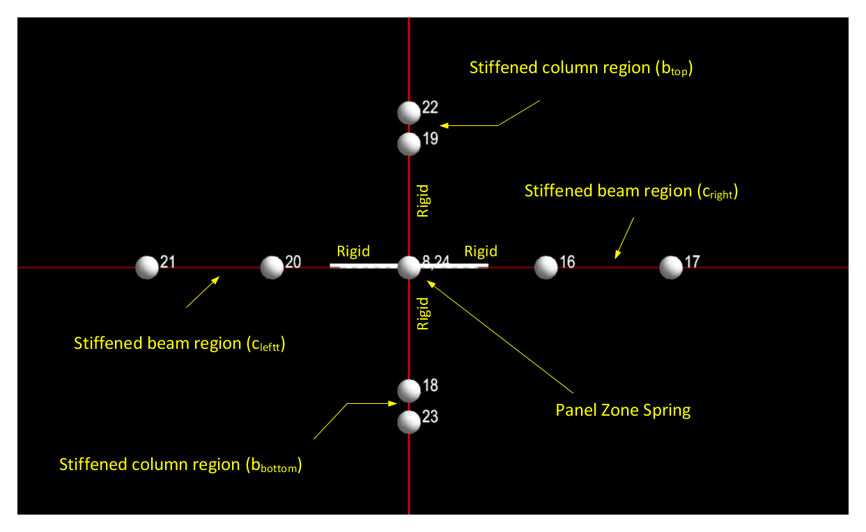
As an example, the following figure is provided to show how the program constructs a DuraFuse® joint. In the figure, it is shown that beam and column members are broken into sub-elements in which each sub-element has unique stiffness properties according to the rules mentioned above. At the center of the joint, a panel zone spring element is inserted. It may be noted that there exist two nodes (Node 8 and 24 in the figure) at the same location, which are used to create the Scissors panel zone model to capture shear deformations within the panel zone area.

Beam and Column Geometry Check
When a DuraFuse ® connection is assigned to a lateral beam, the beam and column must be geometrically compatible. The program uses the following to check the beam-column geometric compatibility:
where| = | ||
| = | ||
| = |
If the beam and column geometry check fails according to the equation given above, the program additionally checks the following condition:
If this new condition is met, the cover plate thickness is increased as follows:
| tcp = tcp(current) + rounding of a to the nearest plate size |
| = | (bbf + 0.25 – (bcf + 2tcp (current)))/2 |
Beam Column Geometry: Beam cope required for beam m left\right end on Story n.
Verify connection with DuraFuse Frames® prior to finalizing structural design.
Two-Sided Connection Geometry
For a two-sided DuraFuse® connection, beam depths must be equal in depth or have a
difference in depth greater than 6 inches to accommodate installation of plates and
bolts (see beams m1 and m2 on story n).
Verify connection with DuraFuse® prior to finalizing structural design.
DuraFuse Table
Size s for Column\Beam m on Story n is not a valid DuraFuse® Connection Size.
The Scissors Model
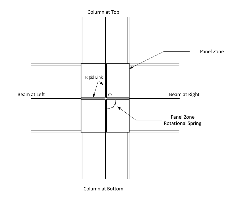
At a DuraFuse® connection joint, a special analytical model is created as explained in the previous sections. Panel zone area, which is composed of the column web and bounded by extension of beam flanges, is exclusively modeled with rigid links and with a panel zone spring.
The panel zone spring is intended to capture shear deformations within panel zone area during analysis. In order to achieve a panel zone modeling within a finite element analysis, the program constructs special nodal arrangements at the center of the panel zone joint: two analytical nodes are created at the same location; one is used to connect the columns (at below and above) and the other node is used to connect the beams (at left and right side). By doing this, it is assumed that the rotations at the column faces on each side of the panel are constrained to be equal. Similarly, rotations at the beam faces on each side of the panel zone are constrained to be the same. However, the rotations at column faces and the beam faces are different.
At these two nodes, translational degrees of freedom (DOF) are locked together (i.e., the nodes move together). Similarly, all rotational DOFs at the nodes are constrained together, except the DOF corresponds to a rotation around an axis perpendicular to the plane of panel zone (i.e., column's web). The unconstrained rotational DOF represents relative rotation between the beams and the columns at the joint.
Finally, panel zone spring element is inserted between the nodes to account for beam-column relative rotation and associated panel zone moment is defined through panel zone spring stiffness (panel zone moment is indirectly related to panel-zone-shear).
It should be mentioned that displacements and rotations are assumed to be small within the aforementioned panel-zone modeling. In addition, local-to-global (or vice-versa) transformations are internally automatically handled by the program.
It is also possible to consider an infinitely rigid panel zone by selecting the option Assume Rigid in the DuraFuse dialog (see the command in ). In this case, panel zone spring stiffness is set to a large numerical value in analysis. This also means that relative rotation between columns and beams at DuraFuse connection joint is zero.In the figure below, a complete view of a DuraFuse joint is given. Note that two nodes are created at Point "O" in the figure (not shown).
In the figure below, beams with DuraFuse connections are framing into column’s flange (strong-axis) and column’s web (weak-axis). Column strong-axis direction is shown with an arrow in the figure. Note that a DuraFuse beam framing into a column’s weak axis is allowed only if column has HSS section type.
The figure on the left shows that there are 3 nodes defined at the joint: node 3 is on the column; node 64 is used to connect the beams framing into the column’s flange and node 65 is used to connect the beams in the other direction. In other words, nodes 3 and 64 are used to define a panel zone element to account for shear deformations within the column’s web. Similarly, nodes 3 and 65 are used to define another panel zone element in the other direction. In the figure on the right below, these two panel zone elements are shown with white and gray colored rectangles (this visualization is used only for the purpose of clarifying modeling concepts and it is not available in the program). Note that the white rectangle represents the panel zone element defined by the beams framing into column’s flange and column’s web area.

|

|
DuraFuse connections defined for column’s strong and weak axes directions
The panel zone modeling approach as detailed above is known as the Scissors Model. There are abundant amount of information on this topic in published literature. The following references are recommended for further information.
References
- 1 Finley A. Charney and Justin Marshall, "A comparison of the Krawinkler and Scissors Models for Including Beam-Column Joint Deformations in the Analysis of Moment-Resisting Steel Frames", Engineering Journal, First Quarter, 2006, pg. 31
- 2 Finley A. Charney and Rakesh Pathak, "Sources of Elastic Deformation in Steel Frame and Framed-Tube Structures: Part 1: Simplified Subassemblage Models", Journal Of Constructional Steel Research, 64 (2008) 87-100