Deflections
Within the RAM Concrete Gravity Analysis mode the beam deflections are generated. There are several steps to the computation of gravity deflections from the original building model. First the full structural model is broken into multiple finite element models, one for each story in the structure. Each finite element model is then loaded with the appropriate gravity loads in specific load cases, and analyzed. Following the analysis, local beam deflections are computed and combined per the code to produce the most accurate gravity deflections. These gravity deflections are then used in the Concrete Beam mode to calculate the final Dead, Live, Long Term and Net Deflections. This technical section describes the details and assumptions made by the program in generating these beam deflections.
Deflection Measurement
Deflections are calculated at 20 evenly spaced stations along the center half of the clear span of each beam. The program assumes that the maximum beam deflection will occur within this length. The displacement at each end of a beam cantilever, where it exists, is also computed.
All deflections calculated in RAM Concrete are based on member local displacement. As illustrated below the affect of beam support displacement (column shortening) does not impact the local member displacement computed for a beam.

Sign Convention
Negative deflection is considered to be an upward acting deflection, while positive deflection is a downward acting deflection.
Skip Loading
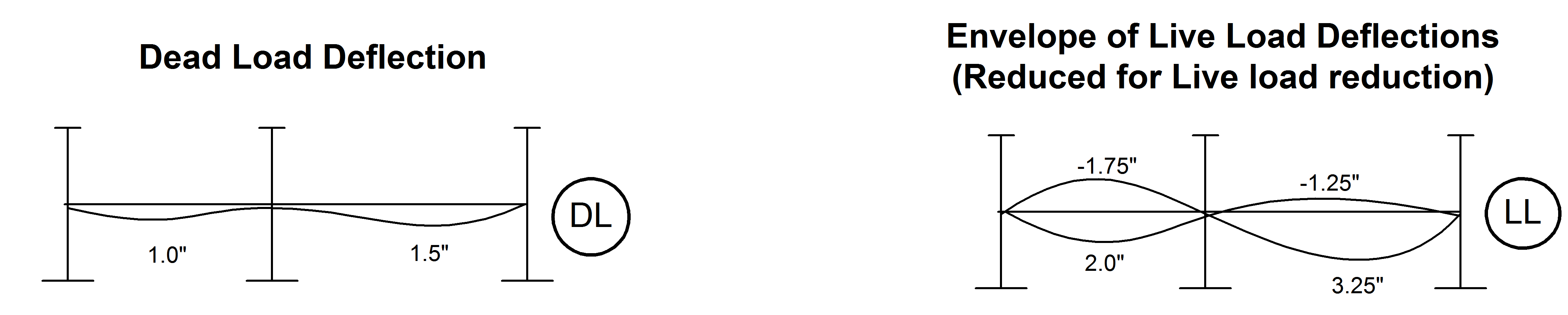
Where specified by the engineer the beams on the structure will be skip-loaded with live load. Similarly to how the program considers beam forces, the live load member deflections from each live (skip) load case are combined so as to produce a maximum upwards and maximum downwards deflection envelope for each beam. This is illustrated in the figure above.
Live Load Reduction
Each of the Building Codes has provisions for reducing the live loads under certain conditions. When appropriate, the program automatically calculates these reduction factors and reduces the loads accordingly. The program recognizes five types of live loads: Reducible, Storage, Unreducible, Roof and Partition. The Roof load may be treated as either Reducible or Snow, as specified by the user in the RAM Manager criteria. The partition live loads are always combined with Unreducible live loads.
Live load reduction factors are a function of the area associated with the loads acting on a member. In calculating the reduction for a given load, the program only uses the area on the member associated with that live load type. For example, if part of the load on a member is Reducible and part is Storage, only the area associated with the Reducible loads will be included in the calculation of the reduction factor on the Reducible loads, and only the area associated with the Storage loads will be included in the calculation of the reduction factor, if permitted, on the Storage loads.

For each (skip) load condition the program will calculate the deflection for each member. Similar to forces these deflections are then reduced by the appropriate live load reduction factor on each span as illustrated above for several skip load cases.
Design Deflection Curves
The individual member live load deflection curves from each load case are combined by summing like-sign deflections on each beam. That is, the analysis of each load case results in either positive (down) or negative (up) deflection at each station along the beam. From each load case the positive deflections are summed and the negative deflections summed (for all live load cases). The result of this process is a live load deflection 'envelope' containing the maximum upward and downward deflection at each station from all skip load cases. Note that unlike for the beam forces, the roof live load deflection is not kept independent of the floor live load deflections. As illustrated below the analysis will produce a single curve for dead load deflections and an envelope of live load deflections for each beam. The live load envelope illustrated below was computed from the skip live load cases illustrated above.
For the case where no skip loading is applied, a single deflection curve (similar to dead load) will be obtained for Live Loads.
Special Conditions
There are a couple of special conditions that need to be considered with respect to the calculation of deflections.
| Setting | Description |
|---|---|
| Pinned Members |
As described previously when a concrete beam member is pinned RAM Concrete internally introduces a rigid element between column face and column centerline. When member deflections are calculated they are based on the member local displacements measured from a line between the supports of the physical beam. As illustrated below the deflection value that is calculated incorporates any rotation that may occur within the support (column), even when the member is pinned. |
| Cantilevers | Deflections are measured at one station located at the end of the cantilever. The cantilever deflection is measured perpendicular to the vector that would extend through the two support nodes of the physical beam as illustrated in the previous section on deflection measurement . |

Shear Deformation
- The member deformation based purely on the end displacements of the finite element are calculated ( in Fig 1b),
- The deformed shape due to any applied point or distributed loads on the member are then calculated. During this second step the end displacements and rotations are considered fixed ( in Fig 1c).
The final element displacement along the member is obtained by combining these two calculated displacements (v = v1 + v2).

In lieu of dividing the member into smaller elements and calculating displacements at required stations, RAM Concrete calculates the displacements ν1 and ν2 by solving corresponding differential equations, considering any end releases, defined rigid ends and any loads on the members. This substantially saves computational time if many member deflection values are required.