Diaphragm Criteria
By default, all floor levels are assumed to be Rigid diaphragms. A rigid diaphragm creates a horizontal constraint for all of the nodes connected to it. For sloped levels, the diaphragm constraint is still horizontal. The size of the diaphragm is dictated by the extent of the slab edge. Since we entered the information for our Semirigid diaphragm in modeler, we will demonstrate now how that information is used.
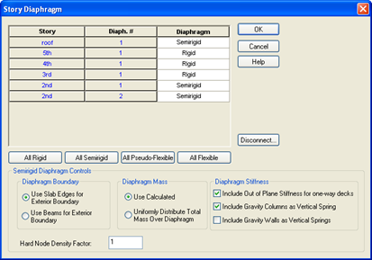
- Click in the cells for the Roof and both diaphragms on the 2nd floors.
- Select Semirigid from the drop down combo box.
- Enter 1 for the "Hard Node Density Factor"
- Leave the other floors as Rigid.
- Click [Disconnect].
- Make sure the option is checked. This means that any lateral elements that fall outside of the slab edge will automatically be disconnected from that diaphragm. Internal nodes on beams occur in places like our chevron braces where the beam is intersected by another lateral member.
- Set the Semirigid Diaphragm Controls at the bottom of the dialog as shown below.
- Click [OK]
- The Semirigid diaphragm uses a Finite Element Mesh similar to the wall mesh for shear walls. To see the floor mesh, click on View-Meshed Floors or use the menu button on the toolbar as seen above.


