Modeling Beam-Column Intersection by Panel Zone Element and Rigid Links
A panel zone element is intended to capture shear deformations within panel zone area during analysis (a panel zone area is defined as the region composed of the column web and bounded by the extension of the beam flanges). A panel zone element can be inserted at beam-column intersection either at column strong-axis or weak-axis direction. It is assumed that weak and strong axis direction panel zone elements are orthogonal to each other and they are uncoupled (i.e., acting independently in their own planes).
Modeling of beam-column intersection involves insertion of panel zone element(s). It is also recommended to include rigid links within the panel zone area (note that panel zone spring stiffness calculation includes effects of rigid link lengths). This type of modeling is portrayed graphically in the following figure.
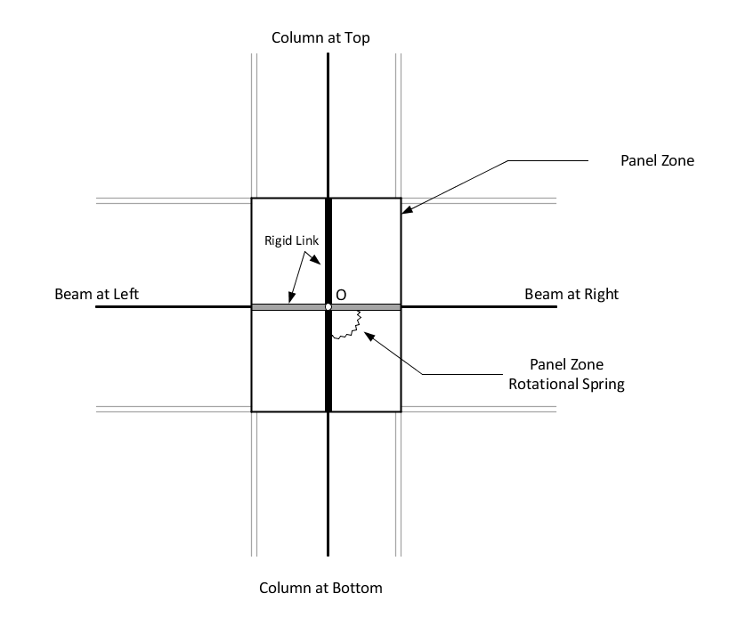
Analytical Model Created for Beam-Column Intersection Joint
In the figure, panel zone element is represented with a rotational spring. This special spring element is intended to capture shear deformations within panel zone area during analysis.
The panel zone analytical model is constructed in a way that the program carries out special nodal arrangements at the center of the beam-column intersection joint: two analytical nodes are created at the same location; one is used to connect the columns (at below and above) and the other node is used to connect the beams (at left and right side). By doing this, it is assumed that the rotations at the column faces on each side of the panel are constrained to be equal. Similarly, rotations at the beam faces on each side of the panel zone are constrained to be the same. However, the rotations at column faces and the beam faces are different.
At these two nodes, translational degrees of freedom (DOF) are locked together (i.e., these nodes move together). Similarly, all rotational DOFs at the nodes are constrained together, except the DOF corresponds to a rotation around an axis perpendicular to the plane of panel zone (i.e., column's web). The unconstrained rotational DOF represents relative rotation between the beams and the columns at the joint. Finally, panel zone spring element is inserted between the nodes to account for beam-column relative rotation and associated panel zone moment is defined through panel zone spring stiffness (panel zone moment is indirectly related to panel-zone-shear).
It should be mentioned that displacements and rotations are assumed to be small within the aforementioned panel-zone modeling. In addition, local-to-global (or vice-versa) transformations are internally automatically handled by the program.
Two options are provided in the program to determine panel zone spring stiffness value. It can be either calculated by the program (only applicable for steel columns) or it can be directly provided by the engineer. If the first choice is selected, the program calculates the spring stiffness, Ks, according to the Reference (1):
where| = | ||
| = | ||
| = | ||
| = | ||
| = | ||
| = | ||
| = | ||
| = | ||
| = | ||
| = | ||
| = | ||
| = | ||
| = | ||
| = | ||
| = | ||
| = | ||
| = | ||
| = | ||
| = |
This type of panel zone modeling is known in the literature as the scissors model. Further information can be found in the following references:
- 1 Finley A. Charney and Justin Marshall, "A comparison of the Krawinkler and Scissors Models for Including Beam-Column Joint Deformations in the Analysis of Moment-Resisting Steel Frames", Engineering Journal, First Quarter, 2006, pg. 31
- 2 Finley A. Charney and Rakesh Pathak, "Sources of Elastic Deformation in Steel Frame and Framed-Tube Structures: Part 1: Simplified Subassemblage Models", Journal Of Constructional Steel Research, 64 (2008) 87-100