Design All and View/Update
With the design criteria set and the load combinations defined, we are ready to design the concrete columns. At this point, the columns should have changed from a light blue color to yellow, indicating that they are ready to be designed. To design the concrete columns:
The design process requires numerous code checks for all of the Load Combinations and may take some time to run on large concrete models. The status indicator again displays the progress of the design and indicates when the design is complete.
The Model graphics will be updated to display the interaction colors similar to Steel Column. Design colors are either Green or Red columns. To see the design colors: View-Colors-Design Colors.
- Green – Indicates that the column was designed successfully with no design warnings.
- Red – Indicates some aspect of the Concrete Column design is insufficient or incomplete. Complete design warnings can be seen in View/Update.
- Blue – Indicates a successful design that is Frozen or Updated. (Columns that have failed will always appear red even if they are frozen.)
- Select .
- With the Target cursor select one of the interior gravity columns (this can be done from any plan view, elevation view or directly from the 3D view).
The View/Update dialog box will open. There are many options available to in this dialog. For a complete explanation of the View/Update window see the RAM Concrete manual.

The Column View/Update dialog box is separated into three tabs for Longitudinal Reinforcement which is initially displayed, Transverse Reinforcement and Material Properties.
The program determined bar pattern is listed in the upper left corner. This reflects the optimum working design from the assigned bar pattern groups. The design can be changed by simply clicking in the cell with the design and picking another set of bars.
On the right side is an interaction surface for the currently selected level of the column. The program creates an interaction surface for each 2-degree increment around the column. When designing the column, the program investigates each data point (a set of axial forces and moments from a particular load combination or pattern). The data point that is closest to the interaction surface is the point initially shown in the diagram.
At the bottom of the widow is an area for design warnings related to longitudinal reinforcement. There is a separate area for transverse design warnings on the second tab.
- Click in the Final Design Pattern cell for the 1st level
- From the drop down list, select 8-#11 (3x1), #5.
- Click [Analyze] to check the validity for the modified design.
The display will update to provide feedback on the success of the design.
- Notice that the program optimized to the 10 bar pattern since none of the 8 bar patterns worked. The 8 bar pattern selected issues a design warning. Feel free to create new bar patterns or edit the existing ones to get a feeling of the design process.
- Click [Close] to return to the main graphic.

The lateral columns in this model have many more design requirements, not only because of the additional loads, but also because they were designated as Special Moment Frames.
In this case, the program selects one of the bar sets with #5 ties. To review the transverse reinforcement click on the Transverse Reinforcement Tab.
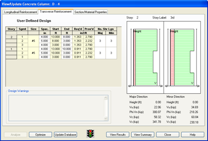
Notice that the shear reinforcement has to be quite concentrated near the ends of the column in order to meet the special detailing requirements of the code.
To review the complete design results.
The Concrete Column Design Report will open. Review the report. For more information on the designs performed in this check refer to the technical portion of the RAM Concrete Manual. Note; with multi-level columns, the report will start from the top level and work down to the base.