Design All and View/Update
With the design criteria set and the load combinations defined, we are ready to design the concrete beams. At this point, the beams should have changed from a light blue color to yellow, indicating that they are ready to be designed. To design the concrete beams:
The design process requires numerous code checks for all of the Load Combinations and may take some time to run on large concrete models. The status indicator again displays the progress of the design and indicates when the design is complete.
Click [Close] to dismiss this window. The Model graphics will be updated to display in design colors.
- Green – Indicates that the beam was designed successfully with no design warnings.
- Red – Indicates some aspect of the Concrete Beam design is insufficient or incomplete. Design warnings that elaborate on why a beam design failed can be seen in the View/Update dialog.
- Blue – Indicates a successful design is Frozen. (A beam that has failed will always appear red even if it is frozen.) In either case, the way to review the details of the design and make changes if desired is through the View/Update command.
- Select and choose the 3rd Floor plan.
- Select .
- With the mouse, select a beam in the southernmost beam line between Grids 3 and 4.
The View/Update dialog box will open as shown below. There are many options available from this dialog. For a complete explanation of the View/Update window see the RAM Concrete manual. For this example, we will touch a couple of the highlights.
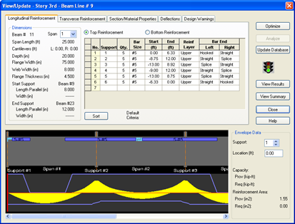
The View\Update dialog is broken into 5 separate tabs. The first tab for Longitudinal reinforcement shows by default. The Top Reinforcement is shown by default.
Notice the diagram at the bottom which graphically indicates the reinforcing and plots the demand envelope (yellow diagram) and capacity (blue line) for the length of the member.
To switch the display to show Bottom Reinforcement:
- Click the radio button near the top labeled Bottom Reinforcement.
The graphic along with the reported Capacity information will be updated.
To see the capacity at a particular location:
- Click on the bottom graphic where the moment diagram is displayed somewhere near the greatest moment.
The red line slider will move to that position and the required and provided member capacity information on the right side will be updated to reflect that particular location.
Changes to the reinforcement can be made in the spreadsheet of reinforcement in the top portion of the dialog.
While reviewing Bottom Reinforcement,
- Click in the Bar Size field for the first bar set
- Increase the bars by one size (#7).
After doing this, the traffic light changes to yellow indicating that the results are no longer current.
- Repeat for the second bar set.
- Click [Analyze] to have the results updated.
The light should still be red in this case indicating that this new layout fails the design checks.
Now we will look at the Transverse Reinforcement.
- Click on the Transverse Reinforcement tab.
Notice that the bottom graphic is adjusted to show shear information rather than bending now.
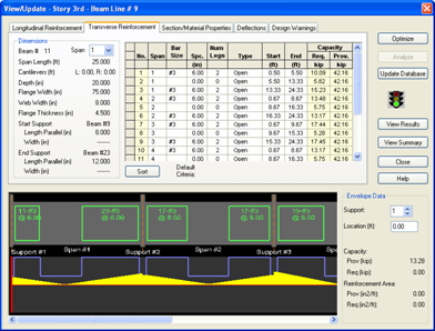
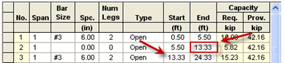
Here the stirrups are grouped into three sections. The first section has #3 stirrups at6" on center and continues for 13' from the face of the column.
- Click in the second row where the bar size is blank.
- Reduce the End location by 3 ft (e.g. from 13.33 to 10.33).
The third row start location will automatically be bumped back as well, making the third bar set longer.
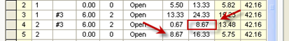
- Click in the 4th row and increase the end location by 3 ft (e.g. from 8.67 to 11.87) Be sure to modify the 5th row to match.
- Click [Analyze] again to review the altered design.
- To see the reported details of the design click [View Results].
The Concrete Beam Design Report will open. Review the report. For more information on the designs performed in this check refer to the technical portion of the RAM Concrete Manual.
- Close the report and return to the View/Update dialog box.
- Assuming the modified design works, click [Update Database] to save the changes.
- Click [Close] to return to the screen display.
If the new design is acceptable, the color of the member will change to dark blue indicating that the design has been modified. This design will not change again unless it is changed manually, or the design is cleared using the Process – Clear Beam Design command.
There are two significant differences about this beam line. First note that the envelope of the demand moments (the yellow diagram) is thicker than the earlier gravity beam. That's because this is a lateral member with more load combinations to consider. The second is the traffic light. If the traffic light is red then some aspect of the design has a warning.
To see what that warning is:
- Click the Design Warnings tab at the top of the window.
This beam happens to have the following warning for each span:
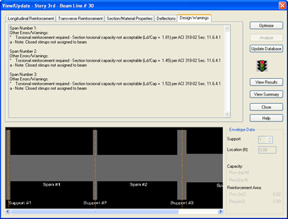
This warning will occur whenever the member Torsion exceeds the minimal capacity of the concrete as specified in the code. It is important to note that the rest of the design is still applicable, despite this warning. To avoid seeing torsion warnings at all:
- Select .
- Click on the Design Checks/Forces tab.
- Uncheck both optional design checks for Torsion and Deep Beams.
- Click [OK].
When you change one of the design criteria you will get a reminder that the designs will have to be rechecked.