Yield-Link Connection
Simpson Strong-Tie Yield-Link® moment frame connection can be assigned to a lateral steel beam member. This type of assignment can be applied to both ends of the beam or to only one end of the beam. Effects of the connection on joint and frame stiffness is automatically determined and applied in the analysis.
Geometry Comparability Condition Checks
Before starting analysis, the program runs a few geometric compatibility checks on Yield-Link beams and produce warning message if any one of them violates predetermined limit. In this section these checks are summarized.
Beam Flange Thickness Check
The program provides the following warning message if beam flange thickness check criteria is not fulfilled:
Beam flange thickness check failed for Yield-Link beam x on story y at beam left/right end.
The beam flange thickness criteria is defined as follows:
where| = | ||
| = |
Beam and Column Flange Width Check
The program provides the following warning message if beam flange width check criteria is not fulfilled:
Beam flange too narrow for Yield-Link size for beam x on story y at beam left/right end (Flange bf_min = xx.x).
Use a wider beam or smaller Yield-Link size.
The program provides the following warning message if column flange width check criteria is not fulfilled:
Column flange too narrow for Yield-Link size for beam x on story y at beam left/right end (Flange bcf_min = xx.x).
Use a wider column or smaller Yield-Link size.
The beam flange width criteria is defined as follows:
The column flange width criteria is defined as follows:
where| = | ||
| = | ||
| = | ||
| = |
The values of bbf_min and bcf_min are obtained from the Yield-Link table based on selected Yield-Link connection size and beam size.
It should be noted that demand to capacity (DCR) is set as 1.05 in this initial check. Initial check is based on the minimum edge distance given in Table J3.4 of AISC 360. When DCR is greater than 1.0 (lesser edge distance than permitted), a detailed check per AISC 360 section J3.10 and J4 will be performed. Edge distance will always be greater than one bolt diameter.
Link Flange Bolt Gage and Column K1 Fit Check (check if Yield-Link fits)
The following warning message is provided if this check is not fulfilled:
Link flange bolt gage and column K1 fit check failed for beam x (beam size) on story y at beam left/right end.
The criteria is defined as follows:
where| = | ||
| = | ||
| = | ||
| = |
Values of WE and Sflange are obtained from the Yield-Link table based on selected Yield-Link connection size and beam size.
K1 value is obtained from AISC database based on column size.
Link Stem Yielding Length Check
The following warning message is provided if this check is not fulfilled:
Link stem yielding length check failed for Yield-Link beam x (beam size) on story y at beam left/right end.
The criteria is defined as:
where| = | ||
| = | ||
| = | ||
| = | ||
| = |
Values of tstem and Ly_yield are obtained from the Yield-Link table based on selected Yield-Link connection size and beam size.
Yield-Link Table
The name of the data table file for Yield-Link connection is YieldLinkData.tbl. This file contains available Yield-Link connection sizes associated with avaialable beam sizes. It is a text file so it can be modified within a text-editor. If beam size selected for a Yield-Link connection is not listed in the table, the program provides the following warning message and then, it does not create Yield-Link connection (the message is also included in the Analysis Log report):
Beam x (beam size) on story y has a Yield-Link connection at its left/right end but no valid connection information is found. Yield-Link connection is ignored at the left/right end of the beam.
Analytical Model Details
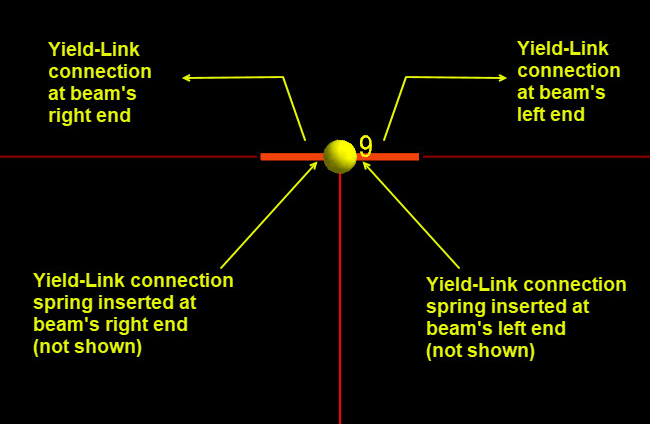
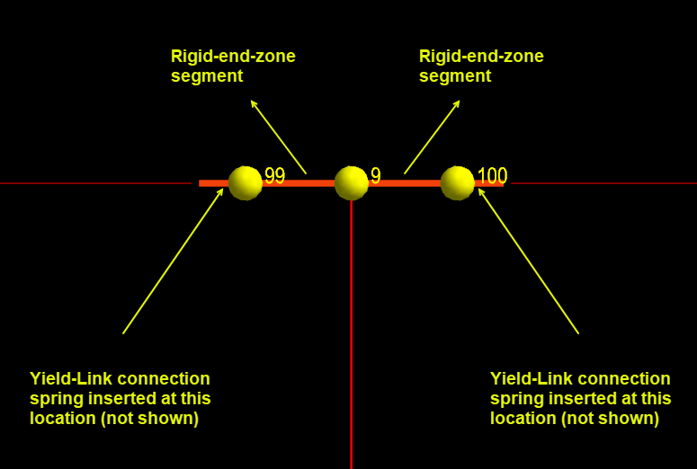
The program creates a special analytical model at locations where a beam with Yield-Link connection is framing into a column. This procedure involves breaking up the beam into sub-elements if rigid-end-zone effects are included and, inserting a connection spring at the end of the beam which represents Yield-Link connection stiffness.
The length of rigid-end-zones can be defined in the General Criteria dialog (i.e., see ). This follows the similar procedure of typical lateral beam with rigid-end-zones (i.e., length of rigid-end-zone is calculated according to a reduction percentage provided by engineer).
Stiffness of Yield-Link connection spring is calculated as follows:
where| = | ||
| = | ||
| = | ||
| = | ||
| = | ||
| = | ||
| = | ||
| = | ||
| = |
Values of tstem and Keff are obtained from the Yield-Link table based on selected Yield-Link connection size and beam size.
In the following figures, examples of Yield-Link connections assigned to beams with or without rigid-end-zones are shown. In these figures, spring connection locations at Yield-Link beams’ end are shown.