The flexural or moment capacity of the beam is checked along the clear length of the beam between supports. The flexural capacity of the beam at any point is:
|
| Equation 3-1 |
|
| Equation 5-2 |
|
c = 0.85fc'abw
| Equation 5-3 |
For concrete compression in the flange of a "T" or "L" section, Mn is adjusted if βc produces compression in the web of the section. The required positive and negative moment capacity is checked against the provided capacity at every output station along the beam between the support faces (refer to the Concrete Analysis manual for information on output stations). All girders, columns, and walls are considered supports and their actual width will be used as the support dimension. This is true even in the case of girders, where for concrete analysis the member is considered a knife-edge support.
The flexural capacity of the beam is considered to be acceptable when adequate reinforcement is provided in the beam to satisfy Equation 5‑4 along the full span length of the beam.
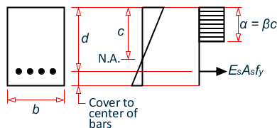
The concrete beam section compression force and reinforcement tension force is calculated assuming a C.S. Whitney Equivalent Rectangular Stress Distribution as outlined in ACI 10.2.7.