RAM Structural System Help

Special Moment Frame

Lateral Concrete Columns

SettingDescription
Geometric Properties Check
SettingDescription
21.3.1.1 If maximum axial load from all the design data points for the column is less than Agf' c/10 a design warning is generated because the member should be designed as a flexural member and not an axially loaded member. When this situation occurs the only way to resolve it are to use engineering judgment to see if it is a valid concern for the given situation or to reduce the size of the column or its capacity at that location. In RAM Concrete Column there is no way to force a column to be designed as a beam. However, in the Design Criteria dialog box on the Design Checks tab there is an option to skip this check during the design process if desired.
Note: The option to check the maximum axial load for column design can be turned off by selecting the proper option under the Design Check tab in the Design Criteria dialog.
21.4.1.1 The column section shortest dimension cannot be less than 12 in.
21.4.1.2 Ratio of short to long dimension cannot be less than 0.4
Flexural Reinforcement
SettingDescription
21.4.3.1 The long reinforcement ratio is limited to between 0.01 and 0.06 rather than up to 0.08.
Shear Design
SettingDescription
21.3.4 The column shear capacity is designed to meet the larger of the analysis factored shear load Vu and the limiting shear induced at the end of the column based on the members probable moment capacity Mpr as outlined in R21.3.4.1
V e = ( M p r ± ) t + ( M p r ) b l n
where
Mpr
=
the max moment capacity (using ϕ = 1.0 and 1.25 Fy) for a given axis for all design points being considered.

However, the value Ve need not be larger than the probable moment capacity of the beams framing into the column in a given direction.

When beams frame into the column:
Mpr=min(Mprc,Mprg)
where
Mprc
=
Column probable moment capacity
Mprg
=
Beam/girder probably moment capacity

This Mpr value is calculated for the top and the bottom part of the column.

The distribution of Mprg to the column is proportional to EI/l of the columns above and below the joint. The program estimates an Split factor to distribute those moments to the column considering the EI/l ratio of the column above or below the joint.

(Mprg)t=(ΣMprlg±+ΣMprrg)×splittop(top)
(Mprg)b=(ΣMprlg±+ΣMprrg)×splitbottom(bottom)
where
Splittop
=
EaIalnaEaIalna+EbIblnb
Splitbottom
=
EbIblnbEaIalna+EbIblnb
Ea
=
Concrete modulus of elasticity (Column above the joint)
Eb
=
Concrete modulus of elasticity (Column below the joint)
Ia
=
Moment of Inertia (Column above the joint)
Ib
=
Moment of Inertia (Column below the joint)
lna
=
Clear span length (Column above the joint)
lnb
=
Clear span length (Column below the joint)

This calculation is done separately for the major and minor axis of column.

Usually the Vu_beams limit controls the design.

The assumption is made that there is uniformly varying shear in-between Ve_top and Ve_bottom. An additional shear diagram is created using the Ve for the top and bottom of the columns which is superimposed onto the shear envelope that was generated from the regular load combinations using the analysis shears.

21.4.4.1 a) Spiral and circular hoop reinforcement must not be less than

ρs = 0.12 f'c / fyh Eq (21-2)

or

ρ s = 0.45 ( A g A c 1 ) f c f h y Eq (10-6)
where
Ac
=
Area of concrete confined by hoop or spiral reinforcement
21.4.4.1 b) For rectangular hoop reinforcement the total area cannot be less than:
A s h = 0.3 ( s h c f c f y h ) ( A g A c h 1 ) Eq(21–3)
A s h = 0.09 s h c f c f y h Eq(21–4)
21.4.4.2 Maximum hoop spacing shall not exceed so over a length of l0 measured from the face, where so is the smaller of:
  1. 1/4 of the smallest cross-sectional dimension of the member
  2. 6 times the diameter of the smallest longitudinal bar,
  3. Sx = 4 + [(14 - hx)/3]

    6 ≥ sx ≥ 4

Wherel0 is at least the larger of:

  1. Maximum cross-sectional dimension of the member, and
  2. 1/6 of the clear span,
  3. 18 inches.

For the top segmentl0 is measured from the bottom of the deepest beam framing into the column.

21.4.4.6 For the remainder of the length the hoops shall be placed with a spacing of not more than 6 in and 6 times the diameter of the smallest longitudinal bar.
21.4.5.2 Vs must take full shear along the length l0 when Vu > Ve/2 and max axial load from all load combinations < Ag f’c / 20 similar to SMF beam.
Notes:
  1. Using max axial from all load combinations.
  2. This design constraint may produce two similar shear bar sets in the same column spans with different shear capacities even though the transverse reinforcement bar size and spacing are identical. This is due to the fact that the capacity for one segment may include the concrete shear capacity because Vu is small enough and for the other segment it will not include the concrete shear capacity because Vu is too large.

Joint Capacity Check Strong Column/Weak Beam

SettingDescription
21.4.2 The total column moment capacity at a joint is checked against that of the beams framing into the joint.
M c t + + M c b 6 5 ( Σ M nlg + + Σ M nrg ) Eq 21-1
M c t + M c b + 6 5 ( Σ M nlg + Σ M nrg + )
where
Mct, Mcb
=
Max moment capacity of the top and bottom columns at the smallest axial load in the given direction.
M±nrg, M±nlg
=
Nominal moment capacity of the left and right ends of the girders /beams framing into the joint.

For both the major and minor axis of the column, the equations above are checked and a design warning is generated for the column below if the check does not pass.

Note: Currently the cantilever end of beams is not considered at all in the joint capacity check. It is assumed that no beam exists at that end. This assumption may be changed / improved in future patches.

Column Design Report

For lateral columns some additional report information is provided to help check the design of SMF members.

Strong column-weak beam check in design report

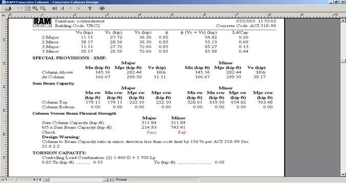
For the column above the story level and the column at (shown below) the story the nominal moment capacity Mn, Probable moment capacity Mpr and the calculated minimum required shear capacity Ve are shown.

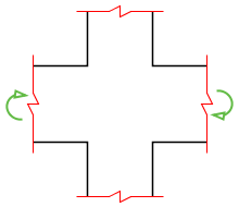
For the column at the story level the moment capacity of the beams framing into the top and bottom of the column are reported for joint rotation in the clockwise (cw) and counter-clockwise (ccw) directions. See Figures below. The value of Mn for beams and columns is calculated using ϕ = 1.0 and 1.25 Fy.

Clockwise Moment at column Joint Counterclockwise Moment at column Joint

The column versus beam flexural capacity, the strong column/ weak beam check, is reported for the major and minor direction of the column.

Joint Shear Check at Column Top

For SMF design there are a number of requirements related to the beam column joint. These checks have been implemented in the column design mode because if the checks fail the most practical way to satisfy the code requirements may be to increase the column section size.

The joint shear capacity check is performed as an independent check and is not part of the main design process. This is to allow the engineer to check if the joint section dimensions are acceptable before designing the column reinforcement.

Icon Description
The option is invoked by selecting the SMF Joint Shear Check from the Column Process menu or by pressing the button on the toolbar. Color coded joints at the tops of lateral columns will be shown. Green - check passed, Red - check failed and Light Blue - data missing or some beams framing into column were not designed. Once the option is invoked the pointer automatically changes to a target so a joint can be selected.
  • 21.5.3.1- The total shear strength of the joint shall not be greater than the following forces for normal weight concrete:
    • Joint confined on all 4 sides ϕ V c = 0.85 ( 20 ) f c A j
    • Joint confined on 3 or 2 opposite sides ϕ V c = 0.85 ( 15 ) f c A j
    • Otherwise ϕ V c = 0.85 ( 12 ) f c A j
    • The beam framing into the joint face is considered to provide confinement if 3/4 of the joint is covered by the member.
    • f'cfor the column below the joint (column at story) is used to calculate the shear capacity.
  • 21.5.3.3 - For lightweight concrete the values in 21.5.3 must be multiplied by 3/4.
    Shear from beam bending capacity on column:
    v h 1 = NumColumnsAtJoint ( M p r l e f t + + M p r r i g h t - 2 ) AverageOfColumnHeightAboveAndHeightBelow
    v h 1 = NumColumnsAtJoint ( M p r l e f t - + M p r r i g h t + 2 ) AverageOfColumnHeightAboveAndHeightBelow

    Vh = max(Vh1,Vh2)

    Total shear in joint from beams is the max of:

    Vu = T1 + T2 - Vh

    where
    T
    =
    1.25AsFy for the top or bottom reinforcement

Joint Shear Check

Notes:
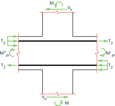
  1. If there are a number of beams framing into the column face the wider beam are used for the check. If beams of the same width are framing into a column the one with the largest sum of M+pr+ M-pr is used.
  2. Currently the cantilever end of beams is not considered at all in the joint shear check. It is assumed that no beam exists at that end. This assumption may be changed / improved in future patches.

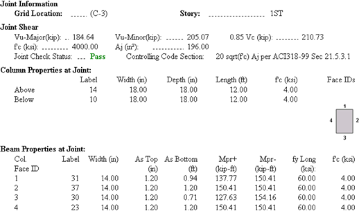
SMF Joint Shear Check Report

The Joint Shear Check report is designed to provide all of the beam and column data that would be required to perform the check.

All of the data in the report can also be found in the beam and column design reports. It is provided in this report for convenience. The column Face IDs diagram under the Column Properties at Joint section is used to reference the location of the beams framing into the column for the Beam Properties at Joint section.

Sample Joint Shear Check Report