Stresses and Internal Forces Summary
This report provides maximum absolute envelope values of wall/diaphragm stresses and internal forces. It is important to note that reported values are maximum absolute values with their sign.
Results for walls can be generated with command. Similarly, provides results for diaphragms.
For each wall, the report gives maximum values of stresses/internal forces found in entire wall. Note that reported values for each stress/internal force type may not be occurring at the same location. (for instance, FMax and FMin may not be at the same location within the same wall).
Similarly, the report gives maximum values of stresses/internal forces of each diaphragm (diaphragm is either semirigid or contains two-way deck). Again, reported values for each stress/internal force type may not be at the same location in entire diaphragm.
In the tables below, reported stresses/internal forces are explained in detail. Note that these maximum values are obtained by reviewing those calculated in all shell elements (located in a wall or diaphragm). In other words, they are not maximum values averaged at nodes. In order to see these values on screen, unselect Stress Averaging and select Show Stress contour values options in the Stress and Internal Force Contours dialog.
The report lists stresses at top\positive and bottom\negative faces separately.
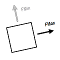
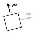
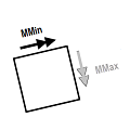

- Principal normal forces are oriented in such a way that associated shearing force is zero.
- Von Mises
principal force is calculated as follows:
where
- ,
= - principal maximum and minimum normal forces, respectively
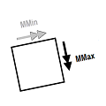
- Principal moments are oriented in such a way that associated twisting moment is zero.
- Maximum
principal shear is calculated as follows:
where
- ,
= - out-of-plane shears, respectively
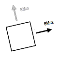

- Principal normal stresses are oriented in such a way that associated shearing stress is zero.
- Maximum principal shear
stress is calculated as follows:
where
- ,
= - principal maximum and minimum normal stresses, respectively
- Von Mises
principal stress is calculated as follows:
where
- ,
= - principal maximum and minimum normal stresses, respectively
- Maximum
out-of-plane shear stress is calculated as follows:
where
- ,
= out-of-plane stresses in the direction of axis on face 1 and 2, respectively.