Brace Points
In the design of steel beams, the program automatically determines the unbraced length of the top and bottom flanges. When a beam frames into a girder, that girder is braced on the top and bottom flange at that location, but when a joist frames into a girder, only the top flange is braced by default.
- Set the Current Material back to Steel.
- Select .
- Type 5 (1.6) for the Distance from selected span end.
- Check the Braces Bottom Flange box only.
- Click [Add].
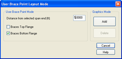
In the graphics mode, select one of the frame beams on Grid Line 4 and then pick at the left end. A yellow triangle on the underside of the beam will appear. If top brace points are placed, the triangle would appear on top.
- Repeat for the other end of the same lateral beam.
- Repeat for both ends of all the moment frame beams on Grid 4.
- Right click to return to the User Brace Point Layout dialog
- Change the Distance to 10 (3.2).
Continue adding brace points until there is one at or near each joist location on all lateral moment frame beams. If you make a mistake select Edit Undo or use the Delete brace point option and remodel.