Floor Slabs and Deck
To complete the physical model it is necessary to apply a slab or deck to the structure. The slab and the deck properties are necessary both to determine composite beam section or T-Beam properties as well as to facilitate the distribution of the gravity load. You do this in two stages, first you will define the properties of the decks and slabs, and then you will layout the slab on the floor. To define the Slab Properties:

On the Composite Floor System tab,
Set the other attributes as follows:
- Concrete Thickness Above Flutes: 2.5 (65)
- Stud Length: 4 (100).
- Unit Weight: 115 (2400).
- f’c: 3 (fcu: 27.5).
- Stud Fu: 60 (450).
- Self-Weight of Steel Deck: 3 (0.15).
- Set the Stud Diam to 3/4 (19).
- Set the Shored option to No.
- Click [Add].
On the Noncomposite Floor System tab, define two noncomposite decks.

- Enter Non Composite-lower for Label
- Enter a deck Unit Weight for Self-Weight of 3 (0.15),
- Leave all other fields blank.
The program is not designing decks at this time, only using the deck self weight in the loads. It is up to the user to make sure the deck selected can span the required distances in the model.
- Click [Add]
- Enter Non Composite –roof for Label.
- Enter 3(0.15) for the self weight again,
- Fill out the Diaphragm properties with the following information:
- Enter 1.0 (25) for Effective Thickness,
- Enter 0.22 for Poisson’s Ratio, and
- Enter 29000 (200000) for Elastic Modulus.
- Click [Add].
On the Concrete Slab System Tab, define three concrete slabs.

- Type 4.5 in 1 way for the Label.
- Type 4.5 (115) for Concrete Slab Thickness.
- Click [Add] and the information will be added to the large window.
- Type 10.5 in 2 way for the label.
- Type 10.5 (265) for Concrete Slab Thickness.
- Click [Add].
- Type Mat Foundation for the Label.
- Type 18 (450) for Concrete Slab Thickness.
- Click [Add].
- Click [OK].
You have now defined the decks/slabs to be applied to the floor plan.
A few notes on decks: ANY Steel members that are under ANY portion of two way deck will not be completely designed. This means that any force coming from the two way slab will be lost to the steel member. Decks can be used as supports for columns, therefore gravity and lateral forces can be applied to other members through the diaphragm. Keep this in mind when placing lateral members in particular as the deck must be meshed to transfer the lateral loads in RAM Frame. Walls cannot be supported by any deck.
We will now apply the decks to the 2nd floor type.
- Select the 2nd level type.
- Select .
- Select the Two-Way option under Slab Action.
- Select the Concrete Framing System Option
- In the list box, highlight the 10.5 in 2 way slab that you defined in the previous step.
- Click [Whole Diaphragm].
- Click anywhere inside the region enclosed by the slab edge (a diaphragm). Do this for both diaphragms on this floor type.

We will layout drop caps on this level as well.
- Right click to return to the Deck Assignment dialog.
- Check the Drop Cap check box to reveal the Drop Cap editor.
- Select the Square button
- Enter 4(1.25) for Size.
- In the list box, highlight the 4.5 in 1 way deck type.
- Click .
This takes you back to the graphics screen.
Notice that the entire floor area is now hatched with an indication of the decking. If the deck on this level had One-Way slab action, lines in the hatch pattern would indicate the span direction of the slab.
- Click on the columns at B-3, B-4, E-3 and E-4.
Notice the different hatch patterns associated with the caps. You can feel free to return to the editor and add rectangular caps to the other columns under the deck if you wish at this point. Also, try the show command described above for checking deck information.

Now layout decks on the other floors.
- Select the 3rd floor type from the drop down combo box.
- Right click to return to the Deck Assignment dialog box.
- Select One-Way under Slab Action.
- Select the 90 degree direction under orientation.
- Highlight the 4.5 in 1-way slab in the list box.
- Click [Whole Floor].
- Right click to return to the Deck assignment dialog and change the Framing System to Noncomposite.
- Ensure that the slab action is still One-Way.
- Select the 0 degree Orientation.
- Select the Non Composite-lower deck type from the list box.
- Click [Add].


This will take you back to the graphics screen.
With the "+" cursor, click at each of the corners of the slab edge around the steel beams that make up the atrium canopy. A continuous white line should appear as you trace out this polygon. Once the polygon is closed the area will be hatched differently that the concrete slab area

The entire floor, except the slab openings, should now be hatched indicating the slab placement. (If the program does not display the deck, it means your slab edge or one of the slab openings are not closed properly. Return to fix that now.). The deck itself is always truncated to the slab edge so it is fine to add deck areas larger than the floor plan as you did here. By making the deck extra large you are assured that the correct deck extends out to the slab edge overhang. This is recommended to prevent unwanted decking on the overhang that might incorrectly brace the perimeter beams.
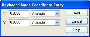
The points that define the deck or slab assignment area can also be established using the Keyboard Mode Coordinate Entry dialog box that appears on screen. The X and Y fields are related to the global coordinate system of the model. Once you have established a node of the deck polygon, those values can also be used to generate an offset, or relative displacement, for the next node. The dialog box can be moved if it is in your way when graphically selecting points.
You can also alter the deck polygon by using the change polygon command in the Deck Assignment Mode dialog.
We will demonstrate that by separating the main concrete deck from the noncomposite deck.
- Right click to return to the Deck Assignment Mode dialog.
- Click [Change Polygon].
- Click anywhere inside the main floor diaphragm and a solid white line will now be encompassing the entire floor. Click on the bottom left hand side of the box at the white node. Click again to move the node to the bottom left slab edge.
- Move the cursor to the midpoint east of the newly moved node. A midpoint node will appear. Click on it and move it to the slab edge near B-1.
- Continue this until the deck polygon looks like this:

Now you can assign decking to the other levels.
We will add the Roof decking once we have altered the pitch of the roof since each sloped plane of the roof will need to be added separately.