Design Envelope
Design Envelope
Major Axis Moments
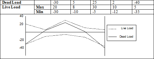
For each load combination the Dead Load, Live Load and Roof Load forces at each station are added together. When the option to skip live loads is selected, it will create a maximum and a minimum force at each station. When live load is included in a load combination, two unique force points are calculated at each station.
For example, in Figure 1, moment values for a beam with 5 stations along its length are shown:
For the Load combination 1.2DL + 1.6L the following two curves are produced:
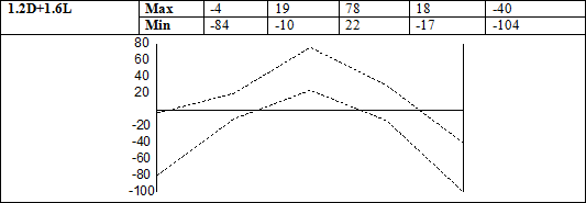
These two curves, obtained from the maximum and minimum moments at each station, are produced for each load combination. Note that for load combinations that do not contain live load the maximum and minimum design force at each station will be the same, as no skip loading is considered for those load cases (it will appear as a single curve if max and min values are plotted together).
All the curves from all the load combinations are then 'enveloped' to produce the largest controlling force at each station (maximum and minimum). Enveloping involves taking the largest and smallest force at each station from all the load combinations. This envelope considers all the skip load conditions and load combinations to provide the upper bound on positive and negative moments on the beam.
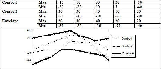 For example, the following two 'curves' from two different load combinations are used to create the final design envelope:
 This is the Final Design Beam Envelope that is used in the design. This envelope will also appear in the View-Update dialog and in the design output report.
Beam envelope design forces in sway frame beams are not currently modified for column slenderness effects per ACI 318-99, 10.13.7. When necessary, the engineer is responsible for confirming the beam capacity is adequate to meet this code provision.
Where forces are required at locations between two stations the values are interpolated from the two adjacent stations.
Shear and Torsion
The same procedure described previously is implemented to calculate beam shear and torsion envelopes. However, as shear and torsion design are not dependent on the direction of the force, the final envelope is then converted into a set of positive design forces computed as the maximum absolute value of the min and max force at each station.
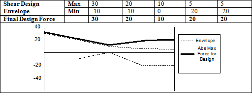
This shear design envelope will appear in the View-Update dialog when the Transverse Reinforcement tab is selected.