Boundary Elements
The Boundary Elements page provides design information related to boundary element design prescribed by the selected design code. If the design code in use has no provisions related to wall boundaries this page will not appear when View/Update is selected. The sheet is split into two tabs: Extents and Tie/Link Design. A discussion of each is given below.
Extends tab
The wall boundary design method that is implemented in RAM Concrete involves limiting the neutral axis of a section under a given axial load to a prescribed value. The Extents page calculates the actual and limit neutral axis distance for each load combination considered during the design. If the neutral axis exceeds the limit, a boundary is required to confine the compression region(s) of the section. The required length of the boundary, projecting at an angle b from the point of maximum compression, is listed in the last column of the spreadsheet. If a boundary is required for a load combination, the corresponding row will be colored red.

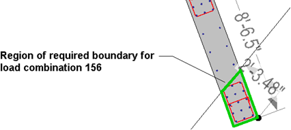
The Design Warnings Page will list all load combinations where the required boundary region encompasses reinforcing zones not designated as boundaries. The user may then adjust the reinforcing zones accordingly to meet the code requirements. For example, for the case shown below, the required boundary region (outlined in green) extends past the zone denoted as a boundary, and thus a design failure will be listed for this load combination on the Design Warnings page.
Tie/Link Design tab
The Tie/Link Design page provides information related to the design of confinement ties for zones specified as boundaries. Zones not specified as boundaries will have no tie design performed. Reinforcing zones are created using the command. Each reinforcing zone is referenced to a Wall Panel and a Section Cut Segment in the calculation page to identify where they occur. The zone start and end locations listed are with respect to the Wall Panel in which the zones occur. The tie size used may be changed in the design code criteria menu.
