Wind Pressure and Inertia Loads on Wall
In RAM Modeler, wind surface pressures and inertia loads can be directly applied on lateral walls (see command in elevation view).
It is a common practice to represent a distributed load on a shell element (such as wind pressure or inertia load) by nodal forces without accompanying moments. This approach is adapted in the current implementation. While it guarantees that no load is missed, moment equilibrium may be not strictly enforced. However, the error due to lack of applying fixed-end-moments diminishes at the expense of using a finer mesh. It should be also known that calculated nodal forces are known as fixed-end-forces that are work equivalent to applied distributed load.
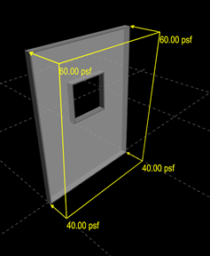
Wind Pressure Loads
A linear wind pressure profile is assumed over height of wall. This means that the program linearly interpolates wind pressure over wall, based pressure values defined at bottom and top of wall. In addition, wind pressures can be defined as toward or away from wall. If a wind pressure is over an opening inside wall, the program provides options to ignore, distribute pressure to vertical sides of opening or distribute pressure to horizontal sides of opening (see command in elevation view).
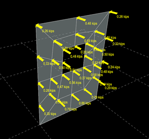
RAM Frame converts wind pressure over a wall into nodal loads applied at wall mesh points when analysis is started (i.e., fixed-end-forces). An example is provided in the following figure: wind surface pressure is defined over a wall in which pressure over opening is distributed to vertical side of the opening. In the figure at right, calculated nodal wind loads are shown, which are based applied wind pressure and wall mesh geometry.
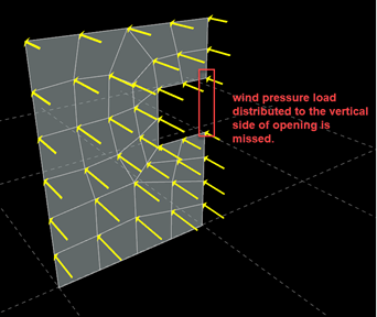
Some pressure loads over opening of wall X at story Y are missed and not considered in analysis for load case Z.
An example for this case is shown in the figure below. The same message is also produced if distribute pressure to horizontal sides of opening and if opening is located at top\bottom edge of wall.

Inertia Loads
| = | ||
| = | ||
| = |
It should be noted that the uniform surface load S is defined as Force/Length2.Finally, the uniform load is converted to nodal loads applied at wall mesh points, as similar to wall wind pressure.