Continuous Footing Optimization
Optimization of Footing Dimensions
Continuous footings are currently optimized for the footing thickness and overhangs on either end of the footing, parallel to the footing's major axis. The footing width parallel to the footing's minor axis is not currently optimized. The dimension optimization is also heuristic and similar in concept to the spread footing.
Thickness is controlled by punching shear and beam shear only when adequate shear reinforcement cannot be found. Footing plan dimensions are controlled by soil stress.
Optimization of Reinforcement
| Setting | Description | |
|---|---|---|
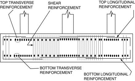
| Flexure Reinforcement | The flexure reinforcement is selected using the same concepts as the spread footing. However, due to the nature of continuous footing design transverse reinforcement is permitted to be a different size than the longitudinal reinforcement. The longitudinal top bar segments are taken between columns. The longitudinal bottom bar segments are taken centered at the column and continuing to the center of each span as required. If a minimum moment is found to be in the middle third of a span it will be used rather than the spans midpoint. Transverse reinforcement segments are taken at column segments, which have the width B ' indicated in Section 4.11.4. The center span transverse segments are taken between column segments. | |
| Shear Reinforcement | For shear reinforcement the footing span between columns is divided into between 3 to 5 segments depending on the length of the segments. If two adjacent segments are found to be too small to practically change the shear reinforcement, the sections are merged. | The cantilevers at either end of the footing are divided into a maximum of 3 segments. |