Wall Openings and Meshing
With the introduction of wall openings the RAM Concrete analysis now performs a meshing of all walls (with or without openings). The mesh is automatically generated without user interaction and the nodes of the meshed wall are visible in the Finite Element Model when displayed on the screen (refer to command). Refer to the RAM Frame manual for specifics on the mesh component and technical information.
For walls with openings that extend to one of the edges the following ramifications will be observed.
Columns at edge of walls with Openings at edge
At locations where a wall opening intersects a column at the edge of a wall the column will be broken into two finite elements at each point of opening intersection or wall mesh (see illustration below where nodes 112 and 113 break the column into three finite elements.
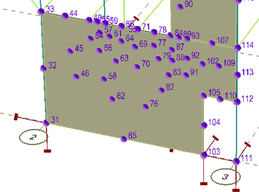
Where this occurs the axial and torsion force used in the columns design will be based on the lowest finite element in the physical column (between nodes 111 and 112).
Openings through the top of walls
Warning! Some load was not successfully applied to a member.
Load is ignored in openings at the top of walls if they exist
The levels and walls at which load has been ignored will be listed in the log/progress dialog which is displayed during and following an analysis.
Openings through the bottom of walls
Nodes located each side of an opening will be assigned boundary conditions similar to those assigned to the ends of the wall. In the figure , node 103 is displayed with vertical and translational fixity as it is located adjacent to an opening. The reaction from these restrained nodes is then applied to the model for the analysis of the story below, and the reactions at these nodes can be displayed from the Process - Results - Reactions command following a successful analysis.