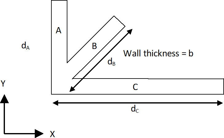
The wall group shown below will be used to illustrate the method adopted.
Calculation of shear capacity vc for the wall group
- Each wall segment will be considered in turn. For each wall segment, the calculation of vc will be made according to the equation in BS8110:1 Table 3.8. The calculation will be performed in the following manner:
- bv will be taken as the thickness of wall (b) immaterial of the orientation of the wall segment.
- d will be measured along the length of wall segment (e.g., dB for wall B above).
- The shear force capacity of the segment will be determined by multiplying the value of vc by (bv.d)
- This shear force capacity will be resolved in the direction of the shear force being considered for design. This implies that wall segments perpendicular to the design direction will not contribute to the shear capacity of the wall group.
- The values of the resolved shear force capacity are summed up for all the wall segments.
- The total shear force capacity is divided by the shear area in the direction of shear force being considered for design to obtain vc.
Determination of the shear area for wall group Av
To determine the shear area in the direction of shear force being considered for design, the following equation will be adopted:
where
|
Σ
| = | represents summation for all wall segments in the wall group |
|
bvproj
| = | is the thickness of the wall projected in the direction perpendicular to the direction of shear being considered for design. This implies that walls perpendicular to the shear direction will not influence Av. |
|
d
| = | is the length of the wall segment along its length |
Calculation of area of shear reinforcement required
The equation given in Table 3.7 of BS8110-1 is utilised:
where
|
v
| = | the shear stress for the wall group calculated as: , with Av calculated as in the preceding section. |