For slab edges (i.e., the area of slab between beam centerline and edge of overhanging slab) in One-way decks, loads are carried back to the beam as if the deck is perpendicular to the beam, regardless of the actual deck orientation. When laying down polygons to define surface loads it is important to lay them down such that they include the slab edge rather than end at beam centerline. If the area between the beam and the edge does not fall inside of a load polygon, no load will be applied. It is permissible to assign a different load to the slab edge than to the opposite bay.
Slab edge lines can be laid out either parallel to neighboring beams, or they can be defined in a free-form. The program carries out a few automated steps to figure out slab edge load polygons, and then computes projected loads within slab-edge load polygons. The projected loads are applied on beams. It should be mentioned that the current implementation works on purely geometric properties of slab edges and neighboring beams even though projecting loads onto beams should involve a more elaborated stiffness based analysis approach. Instead, a simplified approach is applied, which leads to acceptable results for most typical configurations. In the following subsections, the current implementation is briefly described and some limitations identified.
Procedure Detail
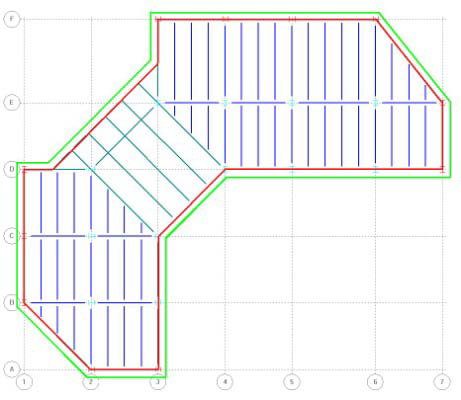
A minimum of two closed polygons are first calculated by the program: a beam-loop polygon and slab-edge polygon (these are indicated in the following figure (A) with red and green lines, respectively). Note that the beam-loop polygon might be composed of beams, joists, or walls. Then the area between the slap-edge and beam-loop polygons is partitioned into load polygons, which are used to distribute loads on slab edges (in the following figure (B) ). These load polygons are generated in such a way that any angle between two beams (or walls) is bisected outward. Finally, any loads (point, line or surface loads) detected on load polygons are projected back onto beams.
|

|
| (A) |
(B) |
(A) Slab-edge and beam-loop polygons are shown in green and red colors, respectively; (B) Generated slab edge load polygons
It is important to know that there must be at least one closed loop with beams (including joist and walls), and one closed loop with slab edges. Otherwise, the program cannot construct load polygons and cannot process loads on slab edges. For some ambiguous configurations, generated load polygons may not be acceptable (to verify loads on edge beams it is recommended that you check the distributed loads found on beams in the
RAM Steel Beam module). An example of such a configuration is given in the following figure; the beams form a concave loop but the slab edge doesn't extend into that area. Thus it is ambiguous as to how the slab edge load and the load within the concave area should be distributed back to the beams. In cases like this it is suggested that the slab edge be placed to more explicitly to identify the intent, or that surface loads be removed from these areas and line loads manually applied to the neighboring members.
Improper load polygon example
Loads (point, line or surface loads) found inside or on these generated slab edge load polygons are projected back to beams (or walls). One-way distribution of loads is assumed, with the slab edge loads carried back to the beam at right angles to the beam. Therefore, loads in the exterior corner of a slab will be ignored since there is no beam to distribute the load back to at a right angle to the beam. For example, the highlighted portion of the surface load in the following figure is ignored:

Loads located within shaded area are ignored

