Process Results Finite Element Information
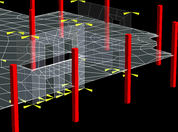
Following an analysis the user can select to display the finite element model that is created for each story of the analysis. Refer to the Manual for specifics regarding the analytical process and the Finite Element Model creation.
Each story in the structure is analyzed independently. The user can use this window to view how each story was analyzed. If the analysis reported an error message it may report a node number of coordinate. The user can use this option to view the story that was being analyzed when the error occurred, so that the location of the error might be observed and action taken to correct the problem.
Note that the display options selected here are only visible on the screen while this window is displayed. The window can be moved and the screen printed or manipulated (zoom etc) while this window is displayed.
Click Apply to have the selected options display on the screen.
| Setting | Description | ||||||
|---|---|---|---|---|---|---|---|
| Story | Select the Story for which you would like to observe the Finite Element Model used in the analysis. When the user selects Apply only the members that were part of the analysis of this story will be displayed. | ||||||
| Mesh | Select this option to display the finite element mesh of the selected story. A quadrilateral element mesh is automatically generated using the criteria specified in the mesh controls. The mesh is always generated for the story at which there are any two way slab-decks. The slab deck mesh is not generated for stories which have only one way slab deck. A slab-deck may have one or more openings defined in the layout. The meshing procedure considers columns as point constraints, beams and walls (above and below) as line constraints and hence always a conformal mesh is generated. | ||||||
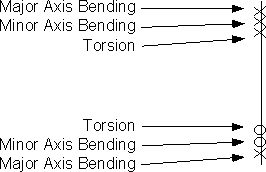
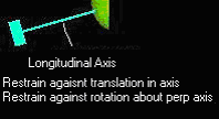
| Beam Fixity | Select this option to display the fixities that are assigned to each physical member for the analysis. The fixities assigned may differ from those observed using the View - Members window as they are modified according to the following: Gravity beams in general are all considered released (pinned) about the major and minor axis at each end, but fixed for torsion. However, gravity (concrete and material 'other') beams can have fixity assigned in the RAM Modeler and RAM Concrete. Frame beams all utilize the fixity they were assigned by the user in the RAM Modeler or RAM Frame. If an instability occurs at nodes of frame or gravity concrete members their fixity may need to be modified in the RAM Modeler, RAM Concrete or RAM Frame. The display convention for beam fixity is 0 = released and X = fixed. The order the fixities are displayed is as follows: |
||||||
| Column Fixity | Select this option to display the fixities that are assigned to each physical column for the analysis. The fixities assigned may differ from those observed using the View - Members window as they are modified according to the following: Gravity columns are assumed continuous at all levels. For pinned gravity columns this should not have a significant affect on the analysis as gravity columns support gravity beams which are pinned (released). Concrete gravity columns are continuous through the story being analyzed. The user can choose to release the base of gravity concrete columns where they frame into the foundation (refer to the Criteria-Analysis for more information. Frame columns all utilize the fixity they were assigned by the user in the modeler or RAM Frame. The display convention for column fixity is 0 = released and X = fixed. The order the fixities are displayed is as follows: |
||||||
| FE Nodes | The physical model created in the RAM Modeler is automatically segmented to create a finite element model. At each location that a member is intersected by any other members it is given a node. By selecting this option the nodes will be displayed. A size slider is provided to change the size of the nodes during the display of the finite element model.
|