Design and Investigation
Beam members are now ready to be designed. The Process – Design All menu item may be selected to perform the design of all beam members or the Process – View/Update menu item may be selected to look at one particular member.
The program will design all beams, C-Beam™ and joists. In order to track beam self weight reactions, the program designed the top level infill beams first, then moves to the girders and then repeats for the levels below.
A dialog box may appear indicating that there are design warnings in the model. If so click [Yes] to review the Design Warnings report. Click the "X" in the corner to close the report.
Design warnings always include the beam number. Beam numbers can be displayed in the Steel Beam module using the command View – Show Beam Numbers.
 A beam can be also by found using the Find-Beam command.
To investigate a selected member size:
- Select .
Notice that the cursor now has a "target" shape. Also notice that at the bottom left corner of the screen there is a prompt for the expected action saying Select a Beam to Edit or Update".
- Click on the beam on Grid D from 2 to 3 (in front of the elevator).
The View/Update Dialog box opens. This dialog box is used to investigate, modify and update the design of single members. You can change size, shape, yield stress, section type, composite flag or stud configuration and re-analyze the beam. For a complete explanation of how the program designs beams refer to the RAM Steel Beam documentation.

To view the loads on the beam:
A Loads Report will come up showing the line and point loads on the beam. When there is a change in the uniform load at a given location, the value is listed just to the left and right of that point.
 to exit the report.
 To view the shear moment and deflection diagrams for the beam:
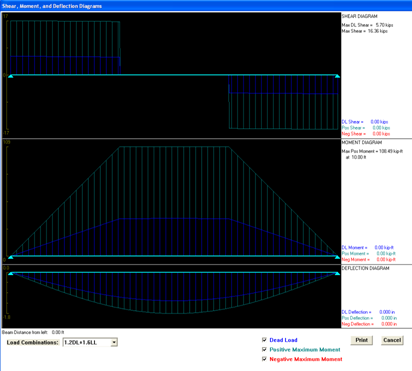
Notice that force and deflection magnitudes on the right hand side reflect the cursor location on the graphic. The mouse automatically controls the cursor when on top of the diagrams. The diagrams for this beam may be printed by clicking [Print] button in this screen.
To inspect the complete design results for the beam:
A Design Report will come up showing various calculations for the beam. This includes information about the composite properties of the member, controlling moments used in the design (along with the applicable unbraced length) and deflections. If the report is more than one page long, click the forward triangle or press the Page Down key to see the next page. Take time to become familiar with this report. This report can also be called in the reports menu at Reports-Beam Design-Single.
To check the design of a different section:
Another dialog box will open showing the new optimized stud configuration based on the new beam size. In this case the required number of studs is less than in the original design. In other situations, the user selected size might produce a design warning.
At this point you can go on to review the loads, diagrams or design results for the new trial section.
To override the optimum selection with this new design
- Click [Update Data Base].
- A warning will appear indicating that the new information will override optimization.
- Click [OK].

At this point you may wish to review other beams or joists in the model. The cantilevered beams on the 3rd and 4th levels and the Joists on the Roof level are of particular interest.
When finished, look into the lower-right corner of the screen. A model status light (a.k.a. traffic light) indicates the status of the model. At this time, the light should be yellow, indicating that there has been some change to the model that has affected reactions on other members. This is the result of changing a beam size in the View/Update dialog. The change in self-weight affects the reactions on other members.
To make sure all the designs are current:
- Select .
Notice that the model status light is now green which means that all beams in this model are designed.
Another way to investigate a single beam is by using the RAM SBeam program. You can export any steel beam from your models to the SBeam program(if currently installed) and investigate resize and design them in a 3-d view not offered in the steel beam module. To do this ensure a current floor layout is displayed, then select Process-Export to SBeam and use the target cursor to select a beam. See the SBeam manual for further instructions on how to use the program.