Optimization
The engineer has many options for controlling how RAM Frame designs stiffeners and web plates (doublers). The engineer can specify minimum values for stiffener dimensions, and web plate thickness. If stiffeners or a web plate are required they will be sized no smaller than the minimum dimensions specified. The increment to which the stiffener dimensions and web plate thickness should be rounded should also be provided. If the stiffener dimension required to resist the forces is larger than the minimum specified stiffener thickness, it will be rounded up to the closest increment. The same applies to the web plate thickness. The maximum permissible stiffener thickness is taken as three times the thickness of the thinnest beam flange framing into the joint. This limit is an arbitrary limit not mandated by any code. The engineer can specify a maximum permissible web plate thickness. If the engineer wants all the stiffeners at a joint to have the same width and thickness, then the top check box should be selected. The maximum thickness and width will be applied to all the stiffeners at a joint, but the lengths may differ.
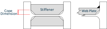
As shown in the following figure the cope dimension refers to the "dog-ear" cut that must be made in the stiffener so that the plate will avoid conflict with the web toe of the column flange-to-web fillet. While this is typically a detailing decision the engineer should (and RAM Frame does) consider this dimension in their calculations, and a conservative value should be specified.
The engineer has a couple of options to specify to the program how the web plates are to be detailed for attachment to the columns. The engineer can choose to weld the plate to the flanges of the column using a CJP weld or a fillet weld. They can also decide to plug weld the web plate to the column web. These user selections are currently only relevant to the AISC code checks.
Where the check box for the fillet weld is not selected, the program assumes that the web plate is attached to the column flange with a CJP weld. The assumption made is that the web plate is cut short of the web toe of the column flange-to-web fillet radius, and the weld is made onto this toe. Alternatively, if the fillet weld check box is selected the engineer is indicating that the web plate is to be welded directly to the column flange. In this case the edge of the web plate will need to be beveled so as to avoid the root of the columns web-flange weld (see the following figure).
To accommodate the detailing requirement of the fillet weld attachment the thickness of the web plate may need to be increased beyond the thickness required just to resist the applied loads (refer to AISC Design Guide 13 for more information).
Note that in the output the thickness required to meet the fillet weld-detailing requirement is specified separately from the design thickness required to resist the loads. Refer to the report descriptions for more details on the output.
The engineer can also choose to plug-weld the web plate to the column web (as is recommended in high seismic zones). If this is done then there are no checks required for web plate buckling. If the engineer indicates that no plug welds are to be used RAM Frame will determine the thickness of the web plate to prevent buckling. This is an AISC code requirement that may control the required thickness of the plate as needed to resist the applied loads.
In general the web plate is designed to resist the applied forces, and the thickness used is controlled by the constraints the engineer provided, the code-specified limits and the detailing requirements. However, some codes have specific limitations on web plate design. Where these specifications have been implemented they are described in the technical section.
Important: Where a web plate is specified by RAM Frame it is assumed the plate extends above and below the top and bottom elevation of the beam flanges respectively. That is, the web plate does not stop at the same elevation as the bottom flange of the deepest beam at the joint, but rather extends some distance below this point. This is important as all checks that considered the contribution of the web plate assume that the plate is effective both above and below the point at which the beam flange applies the concentrated load to the column flange.