Change CS Top Cover and CS Bottom Cover to 3 inches [75 mm], and click OK.
Click the Generate Spans tool (), or choose Process > Generate Spans.
In the Generate Spans dialog box:
Set Spans to Generate to Longitude.
Click the "up-down" orientation button tool ().
Click OK.
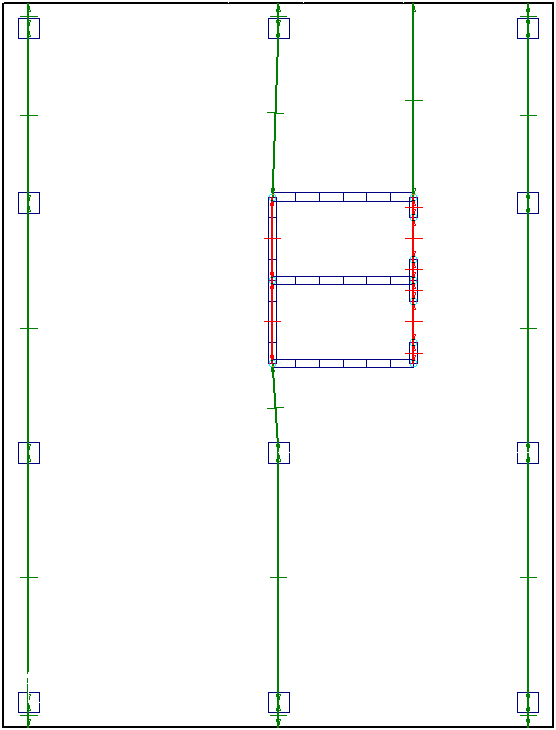
The spans appear in the longitude direction, as shown in the following figure.
Similar to the latitude direction, some editing of the span segments is required.
Design Strip: Longitude Design Spans Plan.
With the Selection tool (), select the span segments over the walls (highlighted in red in the previous figure) and press <Delete>.
Turn on Snap to Intersection ().
With the Span Segment tool (), draw a span segment by clicking at the wall intersections at point A and B in the following figure.
Choose Edit > Selection Properties, or right-click and choose Selection Properties.
In the dialog box, change:
Min Number of Divisions to 0.
Max Division Spacing to 30 feet [10 m], and click OK.
This span segment has been drawn to assist with RAM Concept’s span segment strip width calculation.
Turn on Snap Orthogonal () and Snap Nearest Snapable Point ().
With the Span Segment tool (), draw a span segment by clicking at the wall intersection at point B and then at point C in the following figure (it should snap to the visible grid line).
Choose Edit > Selection Properties, or right-click and choose Selection Properties.
In the dialog box:
Uncheck Detect Supports Automatically.
Uncheck Consider End 2 as Support.
Change Support Width at End 1 to 12 inches [300 mm], and click OK.
 ).
).
 ).
).
 ), or choose Process > Generate Spans.
 ), select the span segments over the walls (highlighted in red in the previous figure) and press <Delete>.
 ).
).
 ) and Snap Nearest Snapable Point (
 ).
).
 ).
).