Draw latitude design strips
- Choose Layers > Design Strip > Latitude Design Spans Plan.
-
Double click the Span Segment tool (
 ).
).
-
The Default Span Properties dialog box opens to the Strip Generation properties.
- Set Column Strip Width Calc to Code Slab (this is the default for the AS3600 template).
- Click the General tab.
- Uncheck the Consider as Post-Tensioned box.
- Click the Column Strip tab.
- Change CS Top Bar and CS Bottom Bar to #8 [N25 for AS3600; T25 for BS8110; H25 for EC2].
- Change CS Top Cover and CS Bottom Cover to 2 inches [50 mm].
- Set the Min. Reinforcement Location to Tension Face.
- Click the Middle Strip tab.
- Check the Middle Strip uses Column Strip Properties box.
- Click OK.
-
Click the Generate Spans tool (
 ), or choose Process > Generate Spans.
- The Generate Spans dialog box opens with Spans to Generate set to Latitude (as shown in the following figure).
-
Click OK.
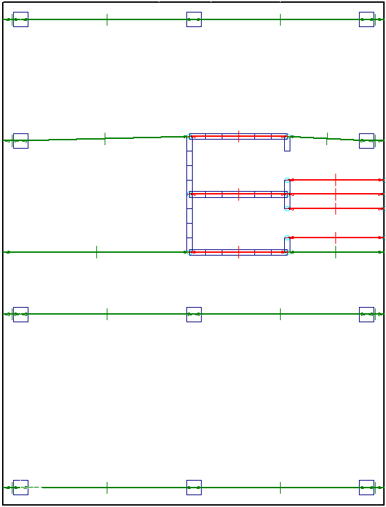
The span segments appear in the latitude direction.
Choosing span segments in a mat is a subjective matter. RAM Concept uses imperfect algorithms that do not always produce acceptable span segments and span segment strips. It is recommended that some span segments in this tutorial are deleted.
-
With the Selection tool (
 ), select the seven span segments highlighted in red in the previous figure and press <Delete>.