Line load properties
The following is a list of RAM Concept line load properties:
| Setting | Description |
|---|---|
| Name | User-defined label used to identify the line load in output. |
| Elevation above slab surface | Vertical distance between the line load and the slab surface. |
| Fx | Line force in the direction of global x-axis (horizontal force). |
| Fy | Line force in the direction of global y-axis at each end (horizontal force). |
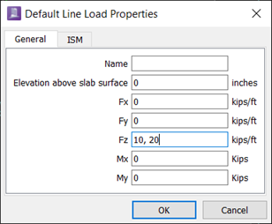
| Fz | Line force in the direction of global z-axis at each end (vertical force). |
| Mx | Line moment about the global x-axis at each end. |
| My | Line moment about the global y-axis at each end. |
Notes:
- If the line force (or moment) is uniform you need to enter only one value. Otherwise you need to enter two values separated by a comma (ends 1 and 2). This allows linear variation of the line force (or moment). See the following figure.
- Although line loads need not be located at a finite element node, you should consider locating very large loads at element edges. Line loads must be completely located on finite elements; RAM Concept issues a warning if you violate this rule.
- Sign convention is defined in . See Choosing Sign Convention .
- Horizontal forces (Fx, Fy) cause applied moments unless the Elevation above slab surface is set to apply the load at the slab centroid.