Calculation of punching resistance for the unreinforced section
Control Perimeter Section Properties and Equations for the Calculation of Actual Stresses
Before any calculations are performed, the following manipulations are carried out on the reactions at the column center:
- The column reactions are transformed to the control perimeter elastic centroid.
- k factors are calculated using ratios about the column principal axes.
- The reactions are rotated to the column principal axes and multiplied by appropriate k factors.
- The reactions are rotated to the control perimeter elastic principal axes.
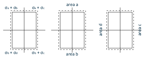
The remainder of the calculations are carried out about the elastic principal axes of the control perimeter. Since a plastic stress distribution is used, if the "punching" area of the control perimeter on each side of the elastic neutral axes is not equal, the magnitudes must vary to maintain vertical equilibrium. This is handled by using multiplication factors representing the ratio of stress on one side of the principal axis over the stress on the other side. These factors are represented in the following form:
The stresses in each quadrant (considering bending about each axis separately) can then be represented as:
| σb = -αx σa | Equation 1 |
| σd = -αy σc | Equation 2 |
Two simultaneous equations can then be set up and solved for the state of stress around the critical section:
M ox = unbalanced moment about the principal x-axis of the critical section (after adjustment by k)
M oy = unbalanced moment about the principal y-axis of the critical section (after adjustment by k)
d = effective depth at location in critical section
| Equation 3 |
| Equation 4 |
We refer to the following terms:
as Zxx
as Zxy
as Zyx
as Zyy
These terms can be envisioned as plastic section moduli and each term has units of cubic length. Due to the interaction of a in the above equations and the equations below, these values are only valid for the axes about which they are calculated.
| Mox = σaZxx + σcZxy |
| Moy = σaZyx + σcZyy |
We can then use equations 1 and 2 to solve for σb and σd .
The stress in any given "quadrant" of the critical section is then solved for as:
Calculation of Allowable Stress
| = | ||
| = | ||
| = | ||
| = | ||
| = | ||
| = |
When ρ1 is automatically calculated for use in equation 6.47, the following apply :
- Reinforcement ratios are calculated about each punch check axis individually.
- A distance 3d beyond the column width is used.
- Only user reinforcement is considered (program reinforcement is not used). Once the flexural design is completed the program reinforcement can be changed to user reinforcement to perform the auto calculation.
- Untensioned reinforcement on the specified face (top or bottom) only is considered (bonded tendons are excluded).
- Vector components of user reinforcement are used.
- Development lengths are considered (only the developed portion of the bar is used).
- A ratio at each face of the column is calculated, with the results of each opposing face averaged. If one opposing face has no reinforcement it is excluded from the calculation (this will be common in edge and corner conditions where reinforcement will cross only a single column face).
- The averaged results in each direction are combined using the equation above.
- If no user reinforcement is detected in a given axis, a warning will be issued and a reinforcement ratio of 0 (zero) will be used.
Calculation of Punching Resistance with SSR
Where SSR is used the punching resistance is calculated as follows:
| vRd,cs = 0.75vRd,c + [1.5(dsw/sr)Aswfywd]/uidi | (6.52) |
| = | ||
| = | ||
| = | ||
| = | ||
| = | ||
| = |
Limitation of Punching Stress at the Perimeter of the Column or Loaded Area
At the perimeter of the column face the maximum shear stress is limited to:
| vEd = vRd,max | (6.53) |
| = | ||
| = | ||
| = | ||
| = | ||
| = | ||
| = |
|
Miscellaneous Provisions
The control perimeter at which shear reinforcement is not required is calculated using eq. 6.47. The outermost perimeter of shear reinforcement is placed not greater than 1.5d within this perimeter.
The spacing to the first stud is calculated as 0.5 d.
The maximum typical stud spacing is 0.75 d.
The maximum transverse rail spacing is 1.5 d within the first control perimeter and 2.0 d outside the first control perimeter.
A minimum quantity of SSR reinforcement is provided in accordance with EC2 equation 9.11:
where st is assumed to be ≤ 2d (Final rail layout should be confirmed/adjusted to be in agreement with this assumption)