Draw latitude design strips
- Choose Layers > Design Strip > Latitude Design Spans Plan.
-
Double click the Span Segment tool (
 ).
).
-
The Default Span Properties dialog box opens to the Strip Generation properties.
- Set Column Strip Width Calc to Code Slab (this is the default for the AS3600 and IS 456 templates).
- Click the General tab.
- Uncheck the Consider as Post-Tensioned box.
- Click the Column Strip tab.
- Change CS Top Bar to #6 [N20 for AS3600; T20 for BS8110; H20 for EC2; T20 for IS 456; 20M for CSA A23.3].
- Change CS Bottom Bar to #5 [N16 for AS3600; T16 for BS8110; H16 for EC2; T16 for IS 456].
- Click the Middle Strip tab.
- Check the Middle Strip uses Column Strip Properties box.
- Click OK.
-
Click the Generate Spans tool (
 ), or choose .
-
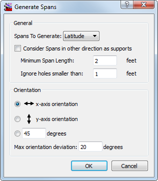
The Generate Spans dialog box opens with Spans to Generate set to Latitude (as shown in the following figure):
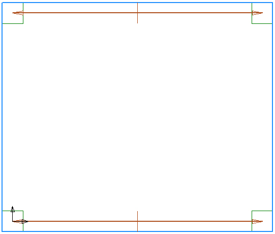
The latitude spans appear, as shown in the following figure.
-
Click the Generate Strips tool (
 ), or choose .
The latitude design strips appear, as shown in the second figure.
), or choose .
The latitude design strips appear, as shown in the second figure.