BS8110 / TR43 specific reinforcement questions
There are a couple of possibilities:
- See "Why is the Minimum Reinforcing required placed on the wrong slab face?".
- TR43 (1st Edition) clause 6.10.5 states that "additional un-tensioned reinforcement shall be designed to cater for the full tension force generated by the assumed flexural tensile stresses in the concrete" for "Support zones in all flat slabs".
The note under TR43 table 2 states that "the support zone shall be considered as any part of the span under consideration within 0.2 x L of the support, where L is the effective span".
This often means that there is tension on the bottom face near the "edge" of the support zone, beyond contraflexure.
Per 6.10.5, RAM Concept adds reinforcement to the bottom face in such instances.
When designing to TR43 (BS8110) with bonded tendons, many designers are surprised to see bottom service reinforcement.
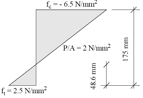
TR43 (1st Edition) clause 6.10.5 states that "…additional un-tensioned reinforcement shall be designed to cater for the full tension force generated by the assumed flexural tensile stresses in the concrete for … span zones in flat slabs using unbonded tendons where the tensile stress exceeds ".
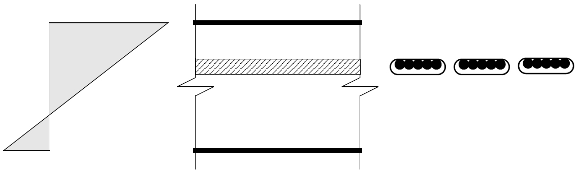
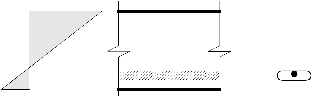
Many designers consider that they do not have to provide un-tensioned reinforcement if they use bonded tendons. However, what they miss is that the reinforcement "shall be placed in the tensile zone, as near as practicable to the outer fibre".
RAM Concept examines the location of the bonded tendons and determines if it is effective. See Calculation of Supplemental Reinforcement Per TR 43, 6.10.5 for further explanation.
The following figures show where bonded tendons would not provide serviceability crack control.