RAM Concept Help

Drawing a bottom reinforcement mat

In this section you are shown how to draw a bottom reinforcement mat and see the ramifications.
  1. Choose Layers > Reinforcement > Bottom Bars Plan.
  2. Double click the Distributed Reinf. Cross in Perimeter tool ().
  3. The Default Distributed Reinforcement Properties dialog box opens.
    1. Note that Elevation Reference is set to Bottom Cover.
    2. Change Elevation to 0.75 inches [25 mm for AS3600, BS8110, IS 456, EC2, and CSA A23.3].
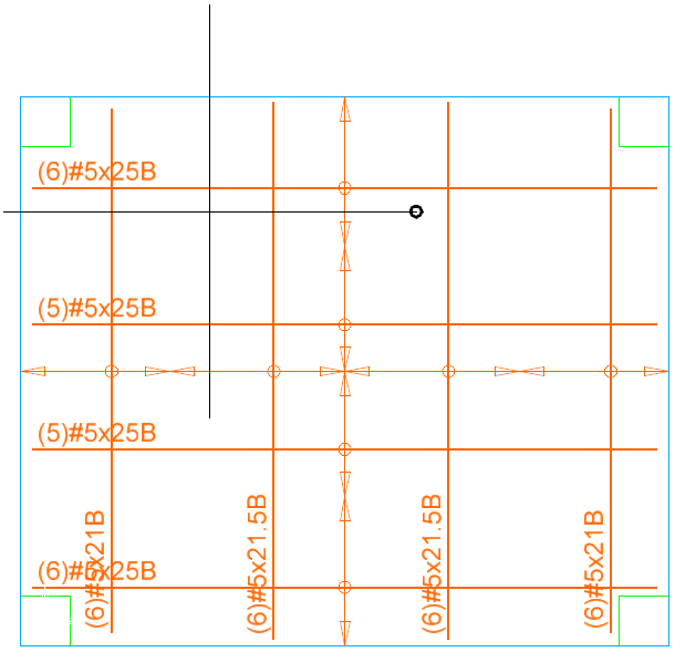
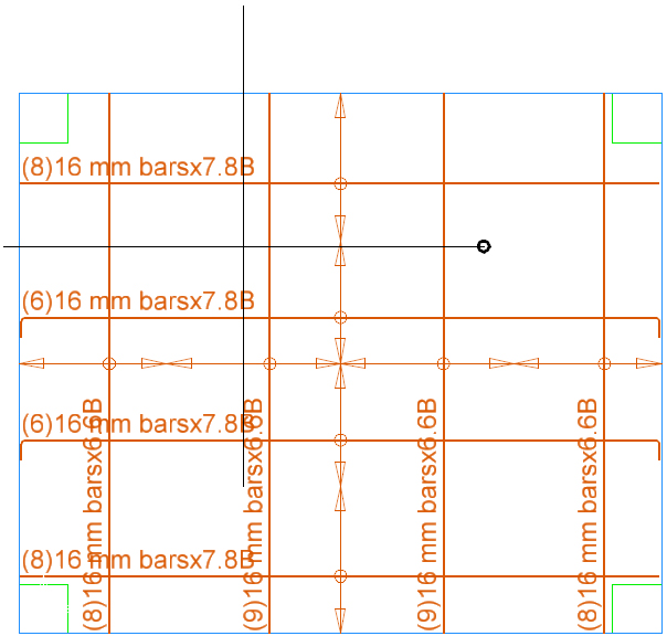
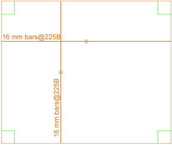
    3. Change Bar Type to #5 [N16 for AS3600; T16 for BS8110; T16 for IS 456; H16 for EC2; 15M for CSA A23.3].
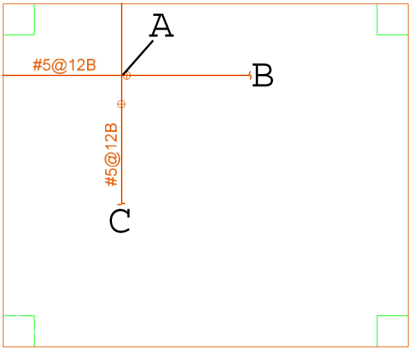
    4. Change Spacing to 12 inches [225 mm for AS3600; BS8110, IS 456, EC2, and CSA A23.3].
  4. Turn on Snap Orthogonal ().
  5. Click somewhere on the slab.
  6. Click at another point to the left or right to define the orientation of the (primary) reinforcement. A polygon appears that is the shape of the slab. Once the file is run you can view the individual bars via the Visible Objects dialog box.
    Note: This creates three objects: a polygon matching the slab outline, a reinforcement object that belongs to the latitude reinforcement layer and a reinforcement object that belongs to the longitude reinforcement layer.
  7. Using the Stretch tool, you can adjust the bar grip postilions for a better appearance.

ACI 318: Reinforcement > Bottom Bars Plan

Bottom mat defined by clicking at points A and B. Point C appears such that AC = AB. The bars are shown to points A and B but the symbol indicates the reinforcement continues to the slab edges.

Bottom mat modified by stretching grip points at B and C.

AS3600, BS8110, IS456: Reinforcement > Bottom Bars Plan

Bottom mat defined by clicking at points A and B. Point C appears such that AC = AB. The bars are shown to points A and B but the symbol indicates the reinforcement continues to the slab edges.

Bottom mat modified by stretching grip points at B and C.