How RAM Concept details longitudinal user and program reinforcement
RAM Concept generates individual bars from concentrated and distributed user reinforcement. This facilitates the consideration of the individual bars in its cross section and span design calculations.
Also, the generation of individual bars allows RAM Concept to display program or user reinforcement in perspective drawings.
The bars are still tagged as "user" since they are generated directly from user reinforcement.
RAM Concept also generates individual bars from its concentrated design reinforcement. These program individual bars are for display purposes only and are not used in calculations.
The concentrated and distributed reinforcement is detailed into individual bars in 5 steps as follows:
Step 1 Create a preliminary layout of bars
Using the shape of the reinforcement region (rectangle or parallelogram for concentrated, and polygon for distributed), the reinforcement orientation and the spacing/quantity of bars, RAM Concept determines a preliminary layout of parallel bar locations.
For Concentrated bars, the first and last bars from the edge are always inset by a half bar spacing distance.
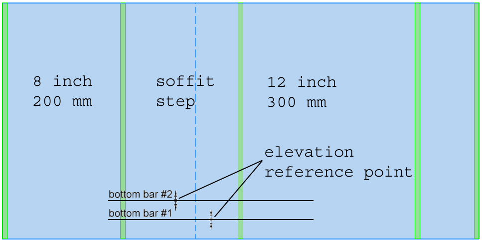
Step 2 Determine the elevation of the bars
Each concentrated or distributed reinforcement callout has an elevation reference point. For Concentrated reinforcement, the elevation reference point is the location where the (symbolic) bar and the extent arrow intersect. For distributed reinforcement, the elevation reference point is shown as a circle in the center of the (symbolic) bar.
The elevation of the surface and soffit of the slab are determined at the elevation reference point and this information along with the reinforcement elevation reference (absolute, above surface, above soffit, top cover or bottom cover) and elevation values determines the absolute elevation of the bars that the callout creates.
Step 3 Determine the slab shape at the bar elevation
For each bar elevation, RAM Concept determines the shape of the slab. This shape may be one contiguous shape or it may be comprised of multiple separate shapes.
Step 4 Trim the preliminary layout of bars with the elevation slab shape
The preliminary layout of bars is trimmed by the slab shape determined in step 3. Additionally, the required end cover (as defined in the General tab of the Calc Options dialog) may shorten a bar further. This trimming may convert a single bar into multiple bars, or may eliminate a bar altogether.
Note that bars with "anchor" ends do not consider the required end cover. They are only trimmed by the slab shape at the bar elevation.
Step 5 Convert the trimmed bar locations to individual bars
Lastly, RAM Concept converts the trimmed preliminary layout of bars into individual bars. This conversion sets the individual bars generated from "user" reinforcement to be "user" bars and those generated by "program" reinforcement to be "program" bars.