Define the manual latitude tendons Pt. 6
-
With the Selection tool (
 ), select the tendon between C-3 and C-4.
-
Click the Calc Profile tool (
 ).
).
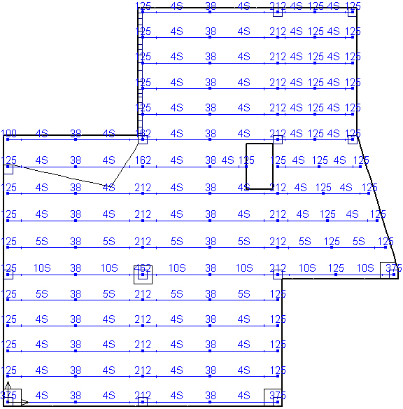
- Input the desired balance load as -6 kN/m in the Calc Tendon Profile dialog box and click Calc. The low point (end 2) adjusts to 126 mm.
-
With the Selection tool (), select all the end span tendons between grids 3 and 5.
- Right click on the plan and choose Selection Properties from the popup menu.
- In the Properties dialog box, set Profile at end 2 to 125 mm and click OK. Finally, you need to adjust the tendon that goes through the opening.
-
Turn on Snap Nearest Snapable Point (
 ) and Snap Orthogonal (
 ).
).
-
With the Selection tool (), select the tendon segment that passes through the opening.
- Right click on the plan and choose Selection Properties from the popup menu.
- In the Properties dialog box, set Profile at end 1 to 125 mm and click OK.
-
Choose the Stretch tool (
 ).
).
- With the one tendon segment selected, stretch the profile point at grid 3 to the other side of the opening.