Question: Why are some tendons shown at the wrong elevation in the tendon perspective?
Answer: The soffit elevation at each profile point is determined during the Analyze All and Calculate All commands. If one of these commands is not performed since the drawing (or moving, etc.) of a tendon, or since a change in the mesh, the tendon elevations in perspectives are not accurate.
The same is true for elevations optionally shown as text on the plans.
It is quicker to analyze (but not using "Calculate All") with . This avoids processing the design calculations.
Question: What do Latitude and Longitude Tendons mean?
Answer: In the USA, Britain and other countries it is typical practice to place all the tendons in one direction in a concentrated band over column lines. If the designer is using another practice then we recommend that you still use the Latitude and Longitude tendon layers because it makes editing the PT easier. i.e. Put the tendons in the X direction on one layer and the Y tendons on the other. Latitude and Longitude are just layer names.
Question: Do I have to draw the tendons for a post-tensioned slab?
Answer: Yes. It is not difficult, and encourages you to address detailing issues before they become field problems.
Question: How do I draw tendons?
Question: Can I harp tendons?
Answer: Yes. Any tendon segment can be declared to be harped. The "half-span" tendon tool is useful for any harp point (or any low point) that is not at mid-span. Multiple harp points can be located in any span by using multiple tendon segments.
Question: Does it matter how I draw half tendons?
Answer: Yes. The inflection point is measured from the first point clicked and the profiles are specified in the order of the points clicked. To be compatible with the tendons created using the Full Span Tendon tool, we strongly recommend that you always start at the high point.
Question: Can I terminate some strands past a column?
Answer: This can be done with one of two methods.
- The tendon can be "forked" such that
the number of strands decreases. As shown in the following figure, if
the transition is from 15S (15 strands) to 10S (because an adjacent span
does not require that many strands) then terminate 5S using a half span
tendon. It is common to terminate strands at quarter span and at the
slab centroid.
Note: You
should only use this method for tendons with no jacks attached. This
is because a jack attached to tendons of different lengths has
inaccurate seating (wedge draw-in) loss calculations.
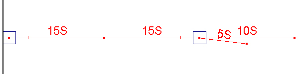
Termination of
strands (no jacks)
- The second method can be used when jacks are modeled. If the total number of strands is 15S then one tendon with 10S needs to be continuous with an additional tendon with 5S alongside. It is common to terminate tendons at quarter span and at the slab centroid.
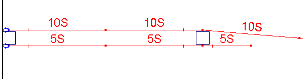
Termination of strands / tendons (jacked). Plan alignment of tendons is subjective.
Question: Does Concept check to make sure the number of strands in connected tendon segments is consistent?
Question: How does Concept calculate friction losses?
Answer: RAM Concept only calculates friction losses if jacks are specified.
RAM Concept performs friction loss calculations considering the (elevation view)
curvature of the tendons, the (plan view) horizontal kinks in the tendon and
the jacking and friction parameters. The stress in the tendon is assumed to
vary linearly along each tendon segment.
Along each tendon the following formula used is:
where
| P1 | = | the known stress at one end of a tendon segment |
| P2 | = | the unknown stress at the other end of a tendon
segment |
| μ | = | the angular friction coefficient (in units of
1/radians) |
| θ | = | the total angular change along the tendon segment |
| k | = | the wobble coefficient (in units of 1/length) |
| L | = | the tendon segment length |
Note: Some engineering
communities (Australia in particular) use a definition of wobble coefficient
that is the accidental angular change per unit length. These communities can
calculate the wobble coefficient that
RAM Concept uses, k, with the following relationship:
k =
AngularWobbleCoefficient × μ.
At the joints between tendon segments RAM Concept uses the following formula:
where
| P4 | = | the unknown stress in the next tendon segment |
| P3 | = | the known stress in the previous tendon segment (or the
jack stress) |
| μ | = | the same angular friction coefficient as above |
| ɑ | = | the total angle change at the tendon profile point
(includes both horizontal and vertical kinks) |
RAM Concept incorporates seating loss (wedge draw-in loss) into the losses using
the standard strain integration formulation. The equations above are still
used, but the known and unknown values are swapped. RAM Concept adjusts the tendon stresses iteratively until the integration of the
strain change in the tendon equals the specified anchorage seat loss.
Long term losses are input by the user as a jack parameter.
See About jacks and Jack properties for more information.
Question: Do I have to specify jacks?
Answer: No. RAM Concept uses the relevant value of fse (specified in the Materials criteria page) as the effective stress for any tendon without a jack.
Question: Does Concept calculate elongations (extensions)?
Answer: Yes, if jacks are specified. Use the Visible Objects dialog to view Jack Elongation on a plan.
Question: Do the elongations (extensions) include the effect of the seating distance (wedge draw-in)?
Answer: Yes. The elongation reported includes the deduction of the seating distance.
Question: Where are tendon profiles measured from?
Question: It's much easier to take all the strands and put them into one tendon bundle instead of having to lay them all out. Is there much difference to the model whether you distribute tendons over the tributary or not?
Answer: This is a matter of engineering judgment. There is certainly no need to lay out individual strands and it is usually satisfactory to group strands in larger tendon groups than that installed in the field. Keep in mind that design strip cross sections consider only the tendons that they cut through to calculate strength etc. There could be instances where you want to model banded tendons in multiple groups (if the band is very wide).
Question: I have laid out the longitude tendons but want to change the number of strands per group. Do I have to lay them out again?
Answer: No. The number of strands in a tendon does not have to be an integer, so you can change it by any increment.
Question: Can I determine the force in a tendon?
Answer: Yes. Use the Visible Objects dialog to view the Tendon Forces on a plan.
Question: Does Concept check for tendons being outside of the concrete?
Question: Do I need to do a load balancing calculation with all the tendons?
Answer: No. The load balance tool is available to help you calculate low points, but is not mandatory.
Question: The load balancing percentage shown on the design strips plan does not make sense. How is this calculated?
Answer: RAM Concept ’s balanced load percentage calculation assumes that what you define as a span, actually behaves like a span. Sometimes this is not the case.
To calculate the effective dead load applied, RAM Concept uses:
where
| D | = | the dead load to be calculated |
| Md | = | the total dead load span moment (calculated from the moments at the first, middle and last cross sections of the span) |
| L | = | the span length (as determined from the span segments, support conditions, etc.) |
The calculation for the effective balance load is similar:
B = 8 Mb / L2
The percentage balanced is 100 . (-B/D)
If, for example, the dead load moments at the start, middle and end cross sections are not negative, positive and negative then percentage balance calculation will not be useful.
This does not mean your strips are wrong, but it might mean that your tendon layout is not doing what you think it is doing. Look at the DL (or DL + LL) deflections (without balance loading) and try to get a better feeling for how the structure is working and from there determine where to add and remove tendons.