Out-of-plane behavior
Out-of-plane forces can be quantified as bending moment about two perpendicular axes, a torsional moment and vertical shears on the two perpendicular faces.
For a differential element the moments and shears are shown as follows:
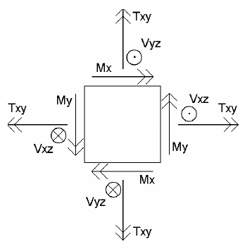
From equilibrium considerations, the variation of the out-of-plane forces can be shown to be:
δVxz/δx + δVyz /δy = -Pz
δMx/δy + δTxy/δx = -Vyz
δMy/δx + δTxy/δy = -Vxz
where Pz is an applied load.
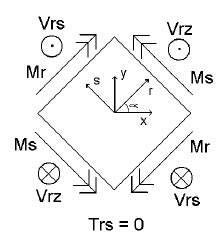
If a different set of coordinate axes is used for references, the moment in terms of these new axes have a Mohr’s circle relationship to the forces in terms of the original axes, the shear forces have a simple vector-like relationship:
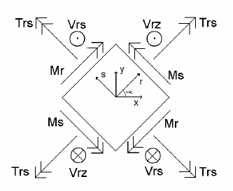
Mr = Mx cos2 α + My sin2 α - 2Txy sin α cos α
Ms = Mx sin2 α + My cos2 α + 2Txy sin α cos α
Trs = Txy (cos2 α –sin2 α) + (Mx – My) sin α cos α
Vrz = Vxz cos α + Vyz sin α
Vsz = -Vxz sin α + Vyz cos α
Again, these relationships are based on equilibrium considerations, so they are valid for all materials.
For every point in the slab there will be a set of two perpendicular "principal axes" where the torsion moments are zero and the bending moments about the two perpendicular directions are at their maximum and minimum values. The angle between the principal axes and the x- and y-axes will vary from point to point in the slab.