Draw a Span Boundary Polyline
-
Select the Span Boundary Polyline tool (
 ).
).
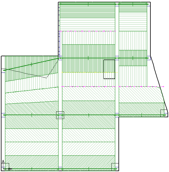
- Click at the intersection of Grid B and Grid C design strips near Grid 2 (point A in the previous figure).
- Click at point B.
- Right-click, and click enter.
- Click at point C.
- Click at point D.
- Right-click, and click enter.
-
Select the Strip Boundary Polyline tool (
 ).
).
- Click at point E as shown in the previous figure.
- Click at point F, to the right of the opening.
- Right-click, and click enter.
- Select the span segment (between grid C2 and C3).
- Right click on the plan and choose Selection Properties from the popup menu.
- In the Properties dialog box, change Span Width Calc to Manual.
- Uncheck Detect Supports Automatically.
- Change Support Width at End 2 from 600 to 610 mm, and click OK This ensures that the first (design strip) cross section passes through the opening, and hence uses less concrete section.
-
Click the Generate Selected Strips tool (
 ).
).