Parts Database Manager
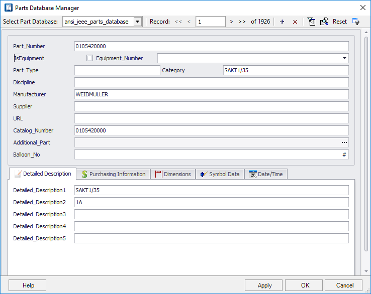
The Parts Database Manager displays the data fields for each part in the database. The user can search for and display parts records, edit or delete existing records and create new records.
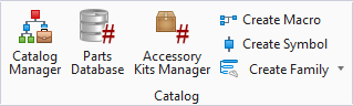
Accessed from:
| Setting | Description |
|---|---|
| Part_Number | This 30 character field holds the number by which the part is identified in the database and when assigning part numbers. Part numbers can include spaces. |
| Equipment_Number | Holds the equipment number which is a type of generic part number that can be assigned until a real part is selected. |
| IsEquipment | Indicates whether the current record is an equipment number (generic) part or a real part. A check-mark indicates a generic part. No check-mark indicates a real part. You can include an equipment number in a real part record so that the software knows that this part is appropriate to use to replace a given equipment number. |
| Part_Type | Use this field to assign the part a part type group of up to three characters. You can filter parts data by the Part_Type field so that only the parts from the selected group(s) will be listed in the Assign Part Number dialog. Usually this field is used to distinguish different types of parts such as TER for terminal blocks, PB for push buttons, etc. |
| Category | Select an existing category from the drop down list or define a new one by entering the name directly into the field. |
| Manufacturer | Select an existing manufacturer from the drop down list or define a new one by entering the name directly into the field. |
| Supplier | Use this 30 character field to enter the name of the company from which you purchase the part. |
| URL | Use this field to attach links to additional
documents, such as equipment specifications. Click the ellipsis button
 to open the
Part Number
URLs dialog. to open the
Part Number
URLs dialog.
|
| Catalog_Number | Use this 30 character field to enter the manufacturer's catalog part number for the part. |
| Additional_Part | Use this field for additional part numbers that are associated with this part. This is useful for parts that are assemblies of multiple parts. These additional part numbers should have their own data records elsewhere in the parts database. When you click inside the Additional_Part field, a Browse button will appear. This button will display the Select Part Number dialog allowing you to select one or more additional parts. |
| Balloon_No | This field defines a default balloon number which
can set to automatically be assigned whenever the Part Number is placed in a
drawing.
The Balloon Settings page in the Project Options interface provides an option to Use balloon numbers from Parts Database which, when set, automatically assigns the balloon number set in this field whenever the part number is placed. |
| Detailed Description | This tab, which is shown above provides fields to define descriptions(s) for the part number. |
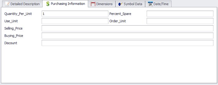
Purchasing Information Tab
This tab provides the fields pertaining to purchasing costs and quantities for the part number.
| Setting | Description |
|---|---|
| Quantity_Per_Unit | This field allows you to determine how many items are represented by the part number when the part number is assigned. The default value is 1. An example for using this field is if you use connector pins that are provided in a bag holding 100 pins. By entering a value of 0.01 in the Quantity_Per_Unit field, you can assign the part number to a single pin in the schematic and it will be counted correctly as one pin rather than one bag of pins. |
| Percent_Spare | Use this field to enter a percentage value to determine how many spares will be ordered for the quantity that is actually used in the design. For example, enter 10 for 10%. These spares are listed in the Project Manager Spare Parts tab. |
| Use_Unit | The units in which the item is used. For example, in the case of pins that are used individually but ordered in boxes, you might enter Pins. |
| Order_Unit | The units in which the item is purchased. For example, in the case of pins that are used individually but ordered in boxes, you might enter Boxes. |
| Selling_Price | Use this field to enter the selling price that you charge for the part. |
| Buying_Price | Use this field to enter the billing price that the manufacturer charges for the part. |
| Discount | Use this field to enter the percent discount. |
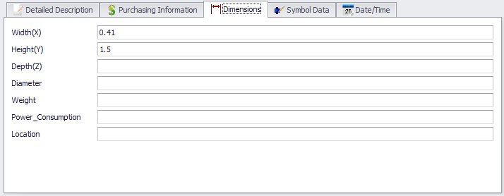
Dimensions Tab
Provides fields to define the dimensions for the part number.
| Setting | Description |
|---|---|
| Width (X) | Enter the X dimension (width) of the part. X and Y values are used to create a box in a panel layout drawing if no layout symbol is named in the Layout field. |
| Height (Y) | Enter the Y dimension (height) of the part. X and Y values are used to create a box in a panel layout drawing if no layout symbol is named in the Layout field. |
| Depth (Z) | Enter the Z dimension (depth or length) of the part. |
| Diameter | Use this field for a diameter dimension for items such as conduits. |
| Weight | Use this field to enter the weight of the part. |
| Power_Consumption | Use this field to enter the power consumption of the part. |
| Location | Use this field to identify the location of components in an enclosure such as panel or door. |
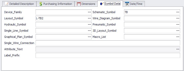
Symbol Data
| Setting | Description |
|---|---|
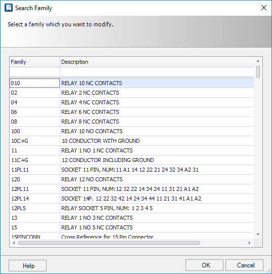
| Device Family | You can assign a device family to the part. If this is done, when the part is assigned to a symbol the device family is automatically assigned to the symbol and there is no need to select a family. In other words, it saves a step when placing parent symbols. You have the option of changing this automatically assigned device family after the symbol is placed. To make an entry in the Device_Family field, click inside the field and select the Browse button that will appear. The Search Family dialog is displayed, which lists the available device families. Select the desired family followed by the OK button. The selected family name will appear in the Device_Family field. |
| Layout_Symbol | Use this field to name the symbol that will represent the part in panel layout diagrams. If no symbol is named here, the part will be shown on panel layouts as a box having the size entered in the Dimensions fields. |
| Hydraulic_Symbol | Use this field to name the symbol that will represent the part in hydraulic diagrams. |
| Single_Line_Symbol | Use this field to name the symbol that will represent the part in single-line diagrams. |
| Graphical Plan Symbol | Use this field to name the symbol that will be placed when a graphical plan is generated if the user includes the terminal symbol variable in his graphical plan template. The symbol itself is defined as a wiring diagram type symbol. |
| Single Wire Connection | A comma-separated list of connection points that will only accept one wire connection. This information is used by the shortest distance wire routing function. |
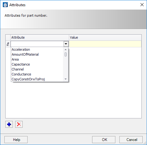
| Attribute Text | Use this field to select a symbol attribute and assign a value to it. Once this is done, if the part is assigned to a symbol that includes this attribute, the attribute value will be assigned to the symbol automatically. To enter a value, click inside the Attribute_Text field and select the Browse button that appears. The Attributes dialog will appear. ' First select the + button to create an attribute entry. Then click inside the Attribute column to display a drop-down list of attributes. Select an attribute and then enter a value of up to 255 characters in the Value column. If you wish to assign another attribute to this part, select the + button. Use the X button to delete assigned attributes. |
| Label Prefix | Enter a value for the label prefix. |
| Schematic_Symbol | Use this field to enter the name of the symbol that will represent the part in schematic diagram. For example, enter the symbol name PBNO for parts that are normally open push buttons (ANSI-IEEE format). This ensures that when the symbol is used in a schematic, the part will be listed in the Assign Part Number dialog. If a part number applies to more than one symbol, you can enter multiple symbol names in the Schematic_Symbol field separated by commas up to the maximum width of the field (example: TBC1,X1). |
| Wire_Diagram_Symbol | Use this field to enter the name of a wire diagram symbol that will represent the part in wiring diagrams. You can click the Browse button in the field to display the Select Symbol dialog allowing you to determine which macro to use. |
| Pneumatic_Symbol | Use this field to name the symbol that will represent the part in pneumatic diagrams. You can click the Browse button in the field to display the Select Symbol dialog allowing you to determine which macro to use. |
| 3D_Layout_Symbol | Use this field to name the symbol that will represent the part in a 3D layout model. You can click the Browse button in the field to display the Select Symbol dialog allowing you to determine which macro to use. |
| Macro_List | Use this field to name the macro that will represent the part in the graphical parts list. You can click the Browse button in the field to display the Select Macro dialog allowing you to determine which macro to use. |
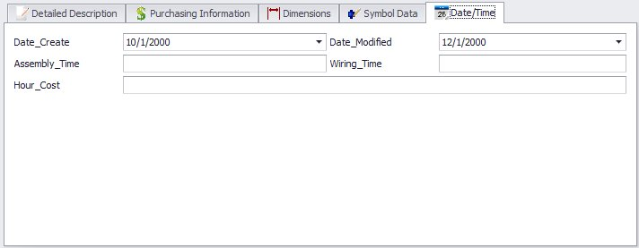
Date/Time
| Setting | Description |
|---|---|
| Date_Create | This field holds the date that the part data was entered in the database. |
| Date_Modified | This field holds the date that the part data was altered (edited). |
| Assembly_Time | Use this field to enter an assembly time value in minutes. |
| Wiring_Time | Use this field to enter a wiring time value in minutes. |
| Hour_Cost | Enter an hourly labor cost. This value can be used in job costing reports. |
Parts Database Editor Functions
There are a number of functions in the Parts Database Editor for accessing and editing data records. Most of these are available in the toolbar at the top of the dialog.
| Function | Description |
|---|---|
| Select Parts Database | Select the database that you are accessing. Database connections are defined in the Promis.e Setup mode. |
| Record Forward/Backward | Use the > button to move forward through the database one record at a time. Use the < button to move forward through the database. Use the << button to move to the first record in the database. Use the >> button to move to the last record in the database. |
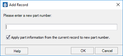
| Add Record | Use the + button to add a
record to the Parts Database. The Add Record dialog will appear.
Enter the part number of the new part. If you wish to use the data of the currently displayed part for the new part, select the check box labeled Apply part information from the current record to new part number. If this check box is not selected, a new record with blank fields is created. Select the OK button to create the new record. |
| Delete Record | Deletes the record currently loaded in the database manager. |
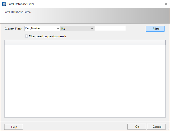
| Filter (Search) | You can find and filter parts
in the parts database by using the
Filter function. Select the Filter
toolbar button in the Parts Database Editor . The Part Database Filter dialog
will appear.
The Custom Filter area of the dialog has three fields: In the far left field, select the parts database field whose value you wish to use for filtering. In the center field, select the comparison
function to be used in the filter. The available comparisons are:
In the far right field, enter the character string that you wish to filter or search for. The like comparison function allows you to use wildcard (*) strings such as PB* for entries beginning with "PB" or *101* for entries containing 101. Select the Filter based on previous results check box if you have already performed a filter operation and wish to filter these results rather than the entire database. Select the Filter button to perform the filtering operation. Any parts that match the filter criteria will be listed in the lower part of the dialog. To display any of the filtered parts in the Parts Database Editor, select the desired part and select OK. You can also double-click on a part number to select it. Note: If you
have performed a filtering operation, and the filter is currently in effect,
the
Filter toolbar button will be
highlighted and the number of records shown at the top of the dialog will be
marked with the word (Filtered). If you wish to remove this filter and access
the entire database again, simply click on the
Filter button.
|
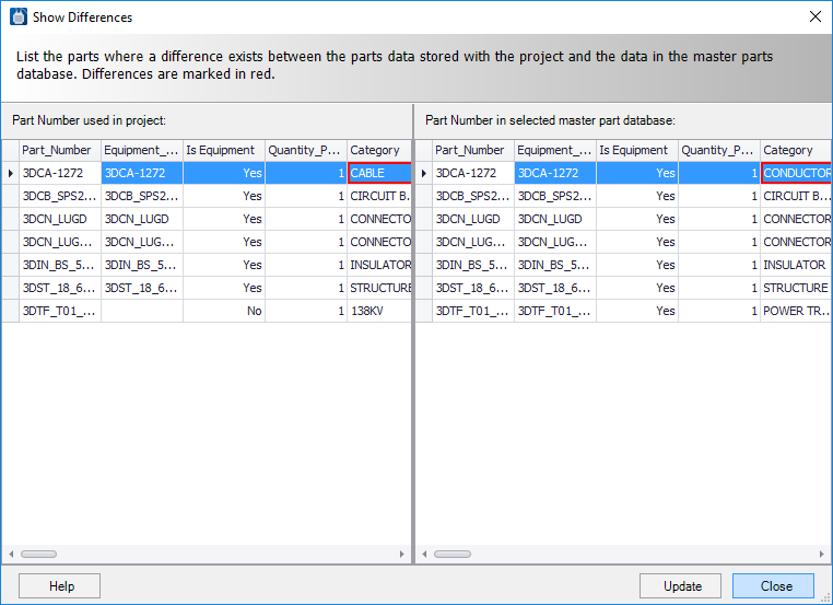
| Show Differences | Data for parts that are
assigned in a project is stored with other project information. If the
information in the parts database is edited, then differences can exist between
the data for a given part number as it exists in the project and in the parts
database.
The Show Differences function will list the parts in the current project where a difference exists between the parts data stored with the project and the data in the master parts database. Select the Show Differences toolbar button in the Parts Database Editor. The Show Differences dialog will appear. If any differences are found in the current project, the affected part numbers are listed. The fields where differences exist are marked in red. To update the parts data in the project, select the Update button. This will copy the data from the master parts database to the parts data in the project. |
| Reset | Resets the record values to their original state. |
| Customize | Displays the Customization dialog letting you modify the layout of the fields in the Parts Database Manager. While new fields cannot be added or removed from the manager, you do have the capability of hiding fields from view. Custom layouts can then be saved to an XML file for reuse. |